Nortec ME Control Installation User Manual
Page 40
40 Installation
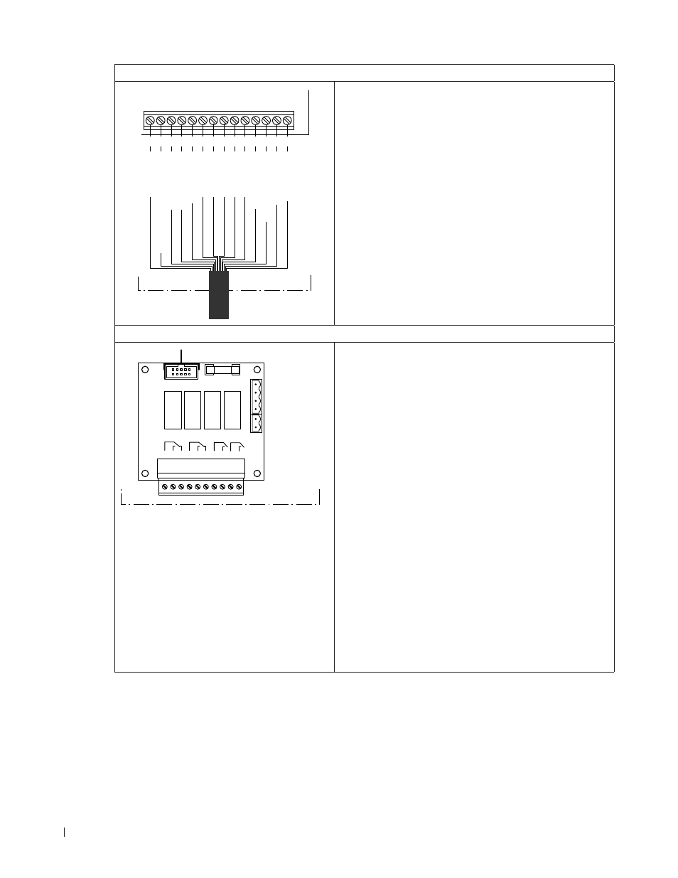
Connecting the 14-core inter-connecting cable from the hydraulic module
K2
X4
1 2 3 4 5 6 7 8 9 10 11 12 13 14
1 2 3 4 5 6 7 8 9 10 11 12 13 14
Level Sensor 1
GND Pumps 4&5, Drain & Sensor
GND Pumps 1,2&3 VCC Pumps 1,2&3
VCC Pumps 4&5
Signal Pump 4 Signal Pump 2 Signal Pump 1 Signal Pump 3 Signal Pump 5
Signal Drain Pump
VCC Drain&Inlet Valve
GND Drain Valve GND Inlet Valve
Control unit
The 14-core inter-connecting cable “K2” from the hy-
draulic module is to be connected according to the
wiring diagram to the terminals “X4”. The 14-core inter-
connecting cable must be fed through the rectangular
cable feed through into the control unit.
Note: The 5 m inter-connecting cable has to be cut to
length on site.
Connecting the remote operating and fault indication (option)
H1
Error
1 2 3
Service
4 5 6
Running
7 8
Unit On
9 10
Control unit
The optional remote operating and fault indication board
contains four potential-free relay contacts for the con-
nection of the following operating and fault indications:
– “Error”:
This relay is activated if an error is present.
– “Service”:
This relay is activated when the set service interval
has expired.
– “Running” (Humidification/Cooling):
This relay closes as soon as the Nortec ME is hu-
midifying/cooling.
– “Unit on”:
This relay closes as soon as the voltage supply to the
control unit of the Nortec ME is switched on.
The connecting cable must either be fed through the
rectangular cable feed through or a free cable gland into
the control unit.
The
maximum contact loading is 250V/8A.
Appropriate suppressor modules are to be used for the
switching of relays and miniature contactors.