Nortec ME Control Installation User Manual
Page 39
39
Installation
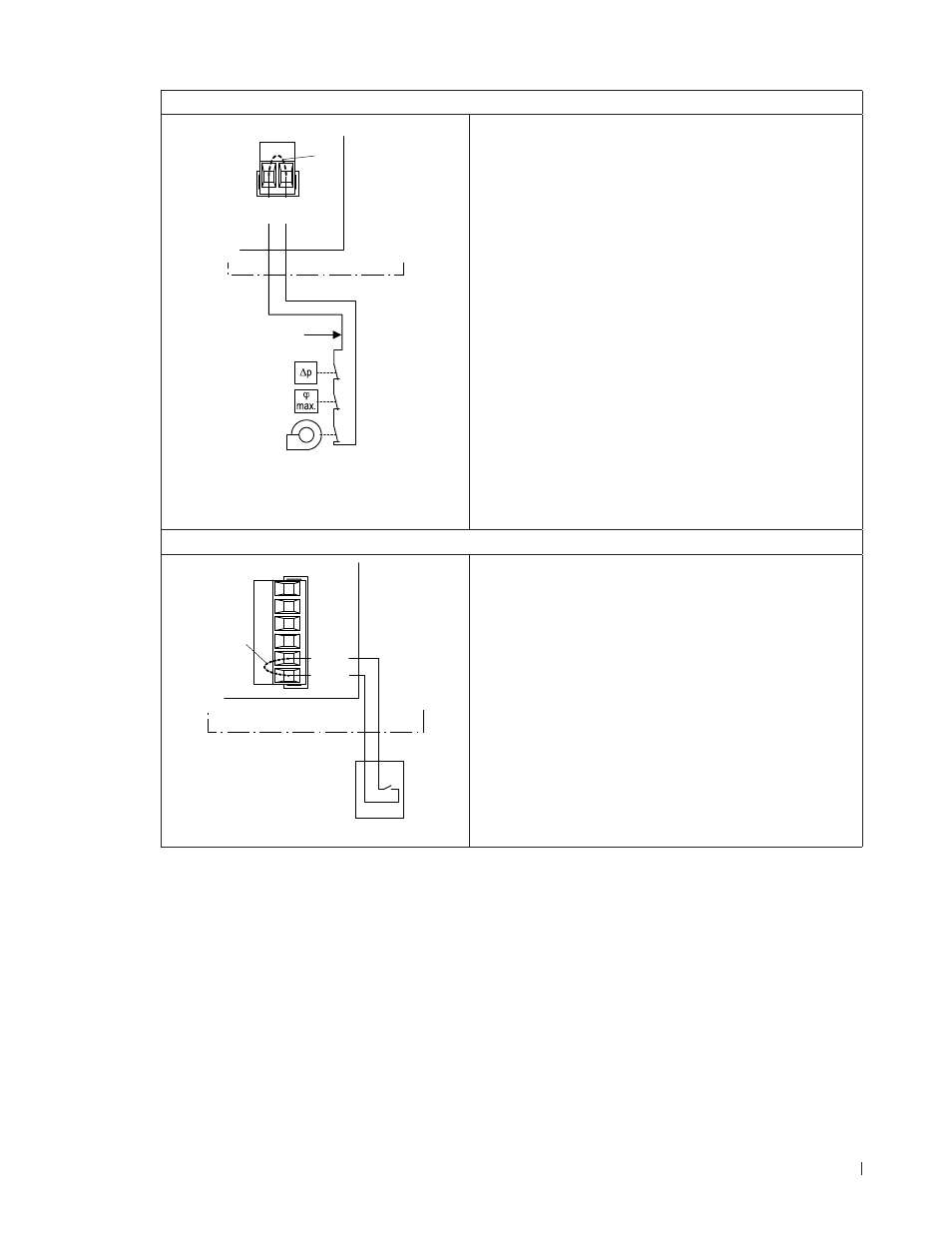
External safety circuit
Control unit
X1
B3
K1
B2
B1
SC2
SC1
J2
To guarantee the safety of the humidification/cooling
system, monitoring the operation by means of a safety
circuit “K1” is an absolute requirement.
To accomplish this, the
potential-free contacts of ex-
ternal moni t or ing devices (e.g. ventilation interlock “B1”,
safety high limit humidistat “B2”, airflow monitor “B3”, etc.)
are
connected in series to the contacts “SC1” and
“SC2” of the terminal block “X1” on the driver board
in accordance with the wiring diagram. The connecting
cable must either be fed through the rectangular cable
feed through or a free cable gland into the control unit.
If, for whatever reason, no external monitoring devices
are connected, a cable bridge “J2” must be installed on
the contacts “SC1” and “SC2” of the terminal block “X1”.
Do not apply any
extraneous voltage to contacts “SC1”
and “SC2” via the contacts of the external monitoring
devices.
The cross-section of the connecting cable must comply
with the applicable local regulations (minimum 1 mm
2
).
External enable
Control unit
X16
24/10V
TMP
GND
HUM
24V E
Enable
S2
J1
The
potential-free contact of an external enable switch
is
connected to the contacts “24 V E” and “Enable”
of the terminal block “X16” on the driver board in ac-
cordance with the wiring diagram. The connecting cable
must either be fed through the rectangular cable feed
through or a free cable gland into the control unit
If no external enable switch is connected, a cable bridge
“J1” must be installed on the contacts “24V E” and “En-
able” of the terminal block “X16”.
CAUTION! Do not apply any extraneous voltage to
terminals via the enable switch.