Troubleshooting the pt-link controller – Orion System PT-Link-LON User Manual
Page 11
PT-Link Interface
PT-Link-LON
®
Technical Guide
11
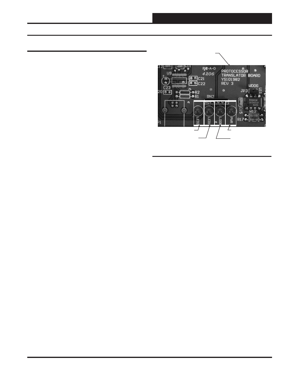
PT-Link Board LEDs
The PT-Link-LON
®
is equipped with LEDs that can be used for trouble-
shooting. There are four LEDs on the PT-Link board. See Figure 18 for
the locations of the LEDs on the PT-Link board. The LED descriptions
and functions are listed in the following paragraphs.
PWR LED
When the PT-Link-LON
®
is powered up, the “PWR” LED should light
up and stay on continuously. If it does not light up, check to be sure
that you have 24 VAC connected to the board, that the wiring connec-
tions are tight, and that they are wired for correct polarity. The 24 VAC
power must be connected so that all ground wires remain common. If
after making all these checks the “PWR” LED still does not light up,
please contact WattMaster Controls Technical Support at our Toll Free
number—866-918-1100—for assistance.
LOOP LED
When power is applied to the PT-Link-LON
®,
the “LOOP” LED will
also light up. The LED should fl icker rapidly, indicating that the PT-Link
is trying to communicate with the controllers on the loop. A “fl icker”
is defi ned as a brief moment when the LED turns off and back on. If the
“LOOP” LED does not operate as indicated above, fi rst power down
the unit and then reapply power. If this does not work, please contact
WattMaster Controls Technical Support at our Toll Free number—866-
918-1100—for assistance.
LED 1
When power is fi rst applied, “LED 1” will be off temporarily and then
will blink once if it is communicating with the controller. If the LED
is not blinking, there is a communication problem between the HVAC
controller and the PT-Link board. The “COMM” LED on the HVAC
controller also should be solid and will fl icker occasionally indicating
communication with the PT-Link-LON
®
. If the “COMM” LED does
not fl icker, then there is no communication between the PT Link and
the controller.
LED 2
When power is fi rst applied, “LED 2” will be off temporarily and then
will blink slowly indicating that the PT-Link baseboard is communicating
with the Protocessor Module. If “LED 2” does not blink, check that the
Protocessor Module is installed correctly in the PT-Link baseboard.
PT-Link Base
Board
LOOP
LED1
LED2
PWR
Figure 18: PT-Link-LON
®
LED Locations
Troubleshooting the PT-Link Controller