Troubleshooting the pt-link controller – Orion System PT-Link-LON User Manual
Page 13
PT-Link Interface
PT-Link-LON
®
Technical Guide
13
Troubleshooting the PT-Link Controller
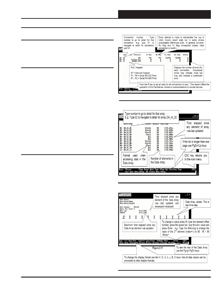
Figure 21: Data Array Overview Screen
Using RUINET
Before continuing with the troubleshooting, make sure the PT-Link is
connected correctly and the RUINET software is installed, running, and
functioning correctly.
Verifying Proper Communications
From the Main Screen, press “O” to go the Connection Overview
Screen. This screen supplies information on communication between the
PT-Link and remote devices. A number of aspect screens are available,
and some of the aspect screens have more than one page. Use the space
bar to toggle between aspects and use the <PgUp> and <PgDn> keys
to toggle between pages of the same aspect. The Connection Overview
and Settings Aspect Screen is shown in Figure 20.
The main purpose in this screen is to verify that messages and characters
are being transmitted and received. In addition, it shows the number of
communication errors. If the PT-Link connection “03” is the protocol
connection, verify that is communicating appropriately. If it is not, check
that the PT-Link LEDs are working properly, the unit is wired correctly,
and the PT-Link is confi gured correctly (Baud Rate, Unit Address &
MAC Address). If the number of errors is constantly increasing, move
to the Error Screen by pressing the <Space Bar> 3 times to fi nd out
the cause of the errors. Use the <PgUp> and <PgDn> keys to toggle
between pages of the Error Screen.
Verifying Proper Values
To verify that the correct values for each unit are being communicated
to the PT-Link, move to the Data Array Overview Screen. To get to
the screen, press “A” from the Main Menu. See Figure 21 for screen
details.
In the Data Array Overview Screen (Figure 21) you will be able to
see the data arrays of all the units connected to the PT-Link denoted by
an array name “DA_XXX_IY”—Y being the address of the unit minus
one. The Address of the unit is determined by a set of dip switches.
To view the values being communicated from a specifi c unit, move to
the Data Array Detail Screen (Figure 22) of the unit by entering the
number under which it is listed. For example, for the unit listed in the
third position, enter “03”.
To understand what each value means, look at the Data Array Tables for
the desired unit type, VAV/CAV, MUA II, or VCM. You can change the
writable values from this screen by using the modify command. To use
the modify command press “M” from the Data Array Detail Screen
and then enter the Offset you want to change followed by a space and
the new value. Example: To change the Cooling Supply Setpoint to 60
in the VAV/CAV, press “M”, enter “58 60”, and then press <Enter>.
This could be useful to prove that the unit can take and keep the set-
points properly.
Figure 20: Connection Overview Screen
Figure 22: Data Array Detail Screen