Confi guring the pt-link controller, Pt-link-lon, Technical guide – Orion System PT-Link-LON User Manual
Page 8: Pt-link interface 8, Explicit and implicit addressing
PT-Link-LON
®
Technical Guide
PT-Link Interface
8
Confi guring the PT-Link Controller
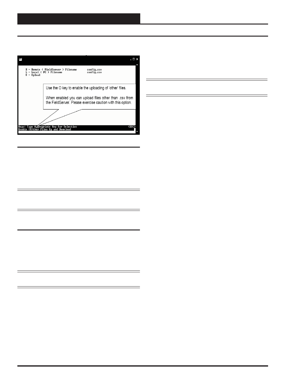
From the Main Menu, type “U”. The menu shown in Figure 12 will appear.
1.) Begin the upload by pressing “U.”
2.) When the upload is completed, open the uploaded fi le with
Microsoft
®
Notepad. This program is supplied with
Microsoft
®
Windows. Type “N” to open using Notepad.
WARNING: Only edit the confi g.sys fi le using Notepad. Do
not use Excel. Using Excel to edit the confi g.sys fi le will corrupt
its contents!
Explicit and Implicit Addressing
Clients can address the PT-Link using explicit or implicit addressing.
Clients using explicit addressing obtain their data transfer parameters
directly from the PT-Link-LON confi guration fi le (confi g.csv). Implicit
addressing is used when a Network Management Tool such as LonMaker®
is used to connect a PT-Link-LON to other LonWorks nodes—the
PT-Link-LON is assigned its data transfer (binding) parameters by the
Network Management Tool.
NOTE: The PT-Link-LON is confi gured from the factory to use
implicit addressing.
Implicit Addressing
— Network Manager assigns addresses for
communication and ensures (via address tables in the devices) that
communication connections are known.
Explicit Addressing
— Device knows the address of the point in
the remote device and communicates directly without the assistance of
the Network Manager.
Figure 12: RUINET PT-Link Uploading Files
Implicit Addressing Commissioning Using
LonMaker
1.) Ensure that the correct fi rmware and latest confi guration is
loaded on the PT-Link-LON.
NOTE: Each change in the PT-Link-LON requires re-commis-
sioning of the PT-Link-LON in LonMaker.
2.) Ensure that the PT-Link-LON and the LonMaker machine
are on the same network.
3.) Open the existing Network in LonMaker or create a new
Network.
4.) Click on “Create New Network” and follow the network
wizard, making the following selections:
Network Interface:
Choose Network Attached
Management Mode:
Choose Onnet unless you are
working
offl ine
Registered Plug-ins required
: None
5.) Once Visio is open with the Network showing, drag a new
device onto the drawing from the toolbox.
6.) Follow the Device Network, making the following
selections:
Enter Device Name
: Choose commission device
Specify Device Template
: Choose upload from device
Specify Device Channel
: Choose Auto Detect
Specify Device Properties
: Leave as is (Ping is optional)
Identify Device
: Choose service pin
Device Application Image
: Leave unchecked
Initial State
: Leave as is
7.) Press the service pin on the PT-Link-LON when asked to
do so, and the PT-Link-LON will be commissioned.
8.) Drag a new function block onto the drawing from the
toolbox. Give the function block a name and ensure that it
is allocated to the PT-Link-LON device.
9.) Once the function block is on the drawing, you can drag
input and output variables onto the function block. When
you do this, LonMaker will show you the variables
avail able for binding. Click on the variables you require
(or use the select “all” option), and they will be
commissioned onto the function block.
10.) You are now ready to connect these variables to other
devices by dragging connections from the toolbox and
connecting the variables.