Confi guring the pt-link controller, Pt-link interface, Pt-link-lon – Orion System PT-Link-LON User Manual
Page 5: Technical guide 5 pt-link hardware connection, Computer ip address set-up for windows 98
PT-Link Interface
PT-Link-LON
®
Technical Guide
5
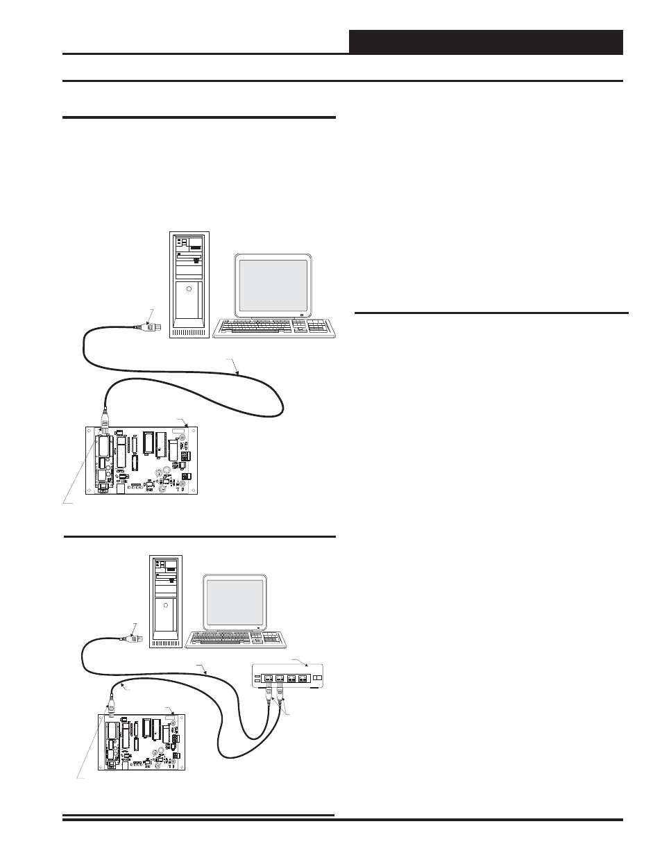
PT-Link Hardware Connection
You have two options for connecting the PT-Link to your PC via Eth-
ernet:
1.) You may connect the PT-Link directly to your PC by using
a crossover cable (by others) as shown. See Figure 3 for
details.
2.) You can also connect both your PC and the PT-Link to an
Ethernet Hub with standard CAT5 cables. See Figure 4
for
details.
Locate a CAT5 cable and plug one end into your computer’s Ethernet
port (use a crossover cable if connecting directly to the PT-Link).
If connecting directly, plug the other end of the Cable into the Ethernet
port on the PT-Link. If connecting through an Ethernet Hub, plug the
other end of the PC cable into the hub, and use a second CAT5 cable
to connect the PT-Link to the hub as well.
Power up the PT-Link by plugging in the power cable. The PT-Link
may take up to three minutes to power up completely. Once the PT-
Link is powered up, you should notice that the green “GPI05” LED
light on the ProtoCessor Board remains on continuously. See Figure
19 on page 12 for a diagram showing the location of the ProtoCessor
“GPI05” LED.
Computer IP Address Set-up for
Windows 98, NT, and XP
In order for the PT-Link to communicate properly, it is imperative to
set the IP address of both the PT-Link as well as the computer to be
within the same netmask. You need to change the IP address on your
computer. The following instructions will explain how to confi gure
the IP address for Microsoft
®
Windows 98 and Microsoft
®
Windows
NT and XP computers.
Computer IP Address Set-up for
Windows 98
1.) From the Windows START button select Start->
Setting->Control
panel.
2.) Double click on the Network icon.
3.) In
the
Confi guration window, select the TCP/IP entry.
4.) Select
Properties and go to the IP Address tab.
5.) Select
Specify an IP address and then enter the
following
information:
a.)
IP
Address
192.168.1.5
b.)
Netmask
255.255.255.0
6.) Select
OK until the network confi guration program exits.
7.) You might have to reboot the computer before the IP
address is valid.
Confi guring the PT-Link Controller
Figure 4: Connecting With Ethernet Cable & Hub
Figure 3: Connecting With Crossover Cable
Ethernet Cable
Ethernet Cable
Ethernet Hub
Connect Ethernet Cable
To Ethernet Hub Port
Connect Ethernet
Cables To Ethernet
Hub Ports
PT-Link Lon Board
Desktop Or Laptop PC
1
2
3
4
Connect Ethernet Cable To
PT-Link Ethernet Port
MADE IN THE USA
WattMaster
CONTROLS, INC
PROTOCESSOR
REV 2
YS101982
PW
R
LO
O
P
LE
D
1
SERIAL #
TRANSLATOR BOARD
DRIV
E
R
EEPROM
PA
L
RAM
EPROM
T
SH
R
LE
D
2
+24VAC
GND
LOCAL
WDOG
TR
AN
SLAT
OR
MOD
U
LE
485
U9
P1
R2
R1
C23
C22
C21
C20
C9
C18
U10
C12
C11
C2
C10
C4
C7
C8
C1
C13
C6
C5
C17
C19
C16
C14
D3
D1
JP3
L1
R9
R3
R8
R6
R7
R12
R17
R23
RN
1
RN2
TB3
U8
U1
U7
U11
U12
X2
X1
TB1
MM1
U6
U4
R4
U5
11.0592
S
F
000103
PC
ROT
O
ESSOR
PC
ROT
O
ESSOR
Ethernet Crossover Cable
Connect Ethernet
Crossover Cable Directly
To PC Ethernet Card Port
Connect Ethernet Crossover
Cable To PT-Link Ethernet Port
Desktop Or Laptop PC
PT-Link Lon Board
MADE IN THE USA
WattMaster
CONTROLS, INC
PROTOCESSOR
REV 2
YS101982
PW
R
LO
O
P
LE
D
1
SERIAL #
TRANSLATOR BOARD
DRIV
E
R
EEPROM
PA
L
RAM
EPROM
T
SH
R
LE
D
2
+24VAC
GND
LOCAL
WDOG
TRANS
L
ATOR
MOD
U
LE
485
U9
P1
R2
R1
C23
C22
C21
C20
C9
C18
U10
C12
C11
C2
C10
C4
C7
C8
C1
C13
C6
C5
C17
C19
C16
C14
D3
D1
JP3
L1
R9
R3
R8
R6
R7
R12
R17
R23
RN
1
RN2
TB3
U8
U1
U7
U11
U12
X2
X1
TB1
MM1
U6
U4
R4
U5
11.0592
S
F
000103
PC
ROT
O
ESSOR
PC
ROT
O
ESSOR