General information, Pt-link interface 3 pt-link-lon, Technical guide – Orion System PT-Link-LON User Manual
Page 3: Data sharing, Hardware specifi cations, Technical data, Table 1: pt-link-lon, Interface technical data, Figure 1: pt-link-lon, Board components and dimensions
PT-Link Interface
3
PT-Link-LON
®
Technical Guide
The OE368-23-LON, PT-Link-LON, provides bi-directional commu-
nication between ONE of the following types of Orion controllers—
VCM-X, SA, VCM, MUA II, or VAV/CAV:
VCM-X Controller (SS1026, SS1030, SS1032,
SS1033, SS1034, Y200920); SA Controller (Y200921)
VCM Controller (SS1016, Y200409, Y200616, Y200822)
*MUA II Controller (Y200405); VAV/CAV Controller (Y200301)
*NOTE: Documentation is available for MUA II/VAV/CAV on
our Orion Controls website: www.orioncontrols.com/
literature-new.html
NOTE: The PT-Link-LON device can be used to connect to only
one Orion controller. If more than one Orion controller is
present in a system, each one will require a PT-Link-LON
device for integration with a LON protocol network.
To determine what controller you have, you must look at the label lo-
cated on the controller EPROM. If the controller label does not match
any of the SS or Y numbers listed above, your controller will not work
with the PT-Link-LON
®
.
Data Sharing
The PT-Link-LON interface provides the following data sharing ca-
pabilities:
•
Provides values from points on the Orion side of the
gateway to LON
®
devices as if the values were
originating from LON
®
objects.
•
Allows LON
®
devices to modify point values on the
Orion controller side of the PT-Link-LON
®
by using
standard
LON
®
write services.
Hardware Specifi cations
Table 1 contains the hardware specifi cations for the PT-Link-LON
®
interface.
Technical Data
LON® Loop
TP/FT-10 (78 Kps)
Controller Loop
RS-485, 9600 Baud Rate
Network Protocol
LONWorks®
Protocol
(WattMaster Loop)
HSI Open Protocol Token Passing
Power Input Voltage
24 VAC
Power Consumption
10 VA Maximum
Operating Temp
10°F to 149°F
Operating Humidity
90% RH Non-Condensing
Weight
8 oz.
Table 1: PT-Link-LON
®
Interface Technical Data
General Information
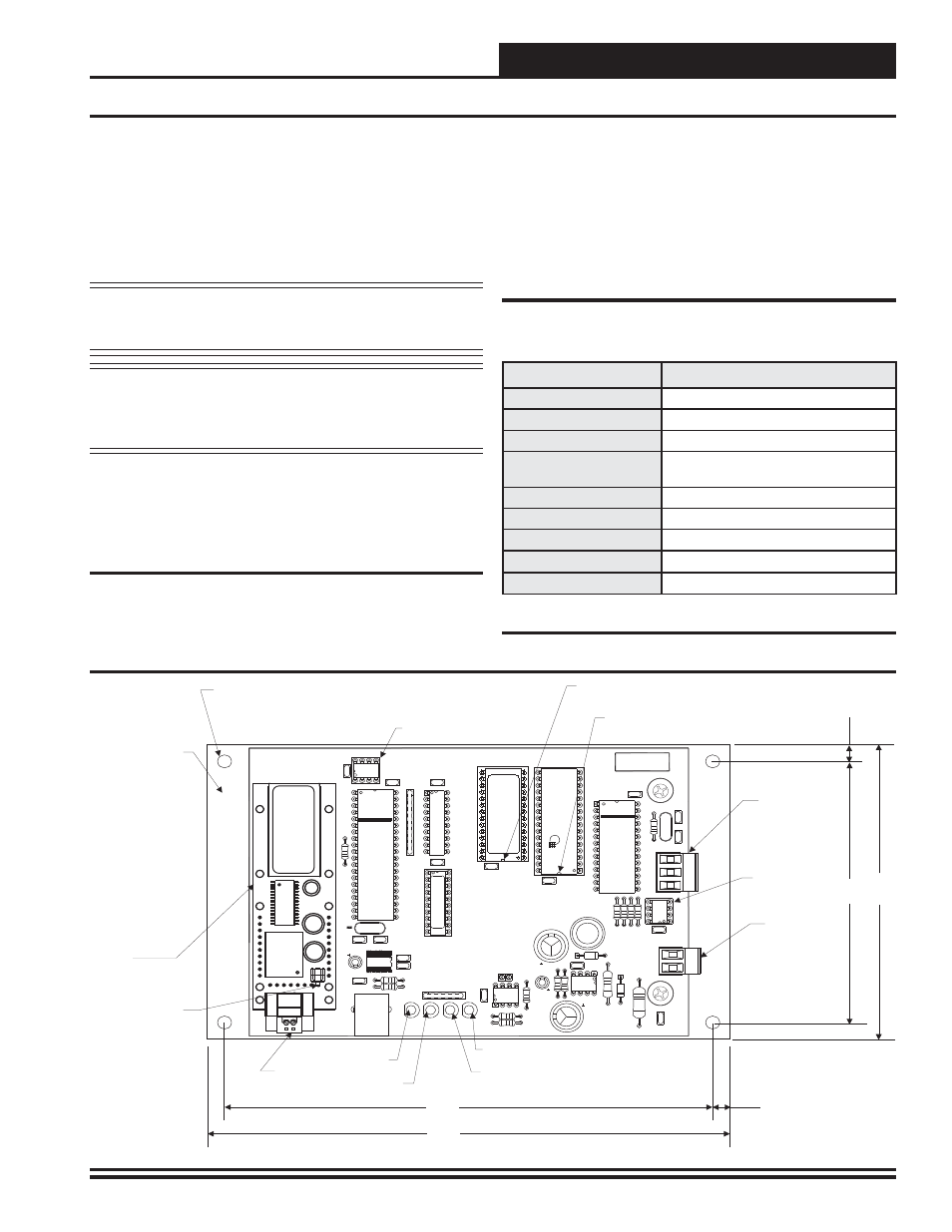
Figure 1: PT-Link-LON
®
Board Components and Dimensions
4.00”
4.50"
0.25”
0.25”
7.00"
7.50"
0.20 Dia.
Mounting Hole
Typ. 4 PL.
Mounting
Backplate
Local Loop
Communications
Wiring Terminal
Local Loop
Communications
Driver Chip
24 VAC Power
Terminals
Communications
LED
Diagnostic
LED #1
Diagnostic
LED #2
Power
LED
EEPROM Chip
EPROM Chip
Pin 1 Indicator
RAM Chip
Pin 1 Indicator
MADE IN THE USA
WattMaster
CONTROLS, INC
PROTOCESSOR
REV 2
YS101982
PW
R
LO
O
P
LE
D
1
SERIAL #
TRANSLATOR BOARD
DRIV
E
R
EEPROM
PA
L
RAM
EPROM
T
SH
R
LE
D
2
+24VAC
GND
LOCAL
WDOG
TRANS
L
ATOR
M
O
DULE
485
U9
P1
R2
R1
C23
C22
C21
C20
C9
C18
U10
C12
C11
C2
C10
C4
C7
C8
C1
C13
C6
C5
C17
C19
C16
C14
D3
D1
JP3
L1
R9
R3
R8
R6
R7
R12
R17
R23
RN
1
RN2
TB3
U8
U1
U7
U11
U12
X2
X1
TB1
MM1
U6
U4
R4
U5
11.0592
S
F
000103
PC
ROT
O
E
SSOR
PC
ROT
O
E
SSOR
LONWorks
Communications
Wiring Terminal
®
LON
®
Protocessor
Module
Service Pin Button