Appendix d - vcm-x lon parameters, Pt-link interface, Pt-link-lon – Orion System PT-Link-LON User Manual
Page 23: Technical guide 23
PT-Link Interface
PT-Link-LON
®
Technical Guide
23
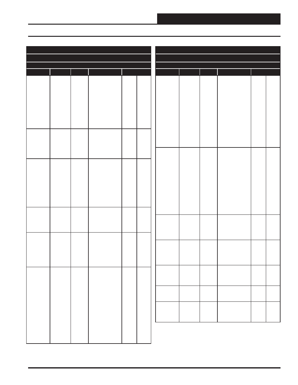
Appendix D - VCM-X LON Parameters
SNVTs for the VCM-X Controller
Binary Output SNVTs are SNVT_lev_disc
all other SNVTs are SNVT_count_inc_f
Parameter
Name
Object
Description
Limits
Warm Up
Setpoint
WmupSt
Analog
Input
In a VAV
application, upon
entering the
occupied mode,
the Warm-up
Demand will be
activated if the
return air tem-
perature falls one
degree below this
setpoint.
Wet Bulb
Setpoint
WtblSt
Analog
Input
The economizer is
enabled if the
outdoor tempera-
ture or wetbulb
falls below this
setpoint.
0
80
Coil
Temperature
Setpoint
CoilTpSt
Analog
Input
This is the coil
suction tempera-
ture target during
dehumidifi cation
mode. Produces
dewpoint in the
supply air
approximately
10°F above this
setpoint.
35
70
Relief
Pressure
Setpoint
RfPrSt
Analog
Input
This is the target
building pressure
to be maintained
by the VFD Relief
signal.
-0.2
0.2
Indoor
Humidity
Setpoint
InRhSt
Analog
Input
If the indoor
humidity rises
above this set-
point, the unit will
activate the
Dehumidifi cation
Demand.
0
100
Unoccupied
Cooling
Offset
UnClOst
Analog
Input
During the
Unoccupied Mode
of Operation, this
Setpoint spreads
the Occupied
Cooling Setpoint
out by a user
adjustable amount.
If you do not want
Cooling to operate
during the
Unoccupied
Mode, use the
default setting
of 30°F for these
setpoints.
0
30
SNVTs for the VCM-X Controller
Binary Output SNVTs are SNVT_lev_disc
all other SNVTs are SNVT_count_inc_f
Parameter
Name
Object
Description
Limits
Unoccupied
Heating
Offset
UnHtOst
Analog
Input
During the
Unoccupied Mode
of Operation, this
Setpoint spreads
the Occupied
Heating Setpoint
out by a user
adjustable amount.
If you do not want
Heating to operate
during the Unoc-
cupied Mode, use
the default setting
of 30°F for these
setpoints.
0
30
CO
2
Setpoint
CO2St
Analog
Input
When the CO
2
level rises above
the CO
2
Protection
Limit Max Level,
the Economizer’s
Minimum Position
will begin to reset
open proportion-
ally between the
CO
2
Protection
Limit Max Level
Setpoint and the
Reset Range
Setpoint.
0
3000
Minimum
Outside Air
Setpoint
MinEcoSt
Analog
Input
This is the
minimum position
of the economizer
in the occupied
modes.
1
100
Static
Pressure
Setpoint
DuctPrSt
Analog
Input
This is the target
duct pressure to
be maintained by
the VFD blower
signal.
0.01
3
Preheater
Setpoint
PreHtSp
Analog
Input
Low Outside Air
Ambient
Protection Set-
point
0
100
Outdoor
Air CFM
Setpoint
OACfmSt
Analog
Input
Minimum desired
Outdoor Air CFM.
0.10 K
200 K
Outdoor Air
CFM Reset
Limit
OACfmRs
Analog
Input
Maximum desired
Outdoor Air CFM
when CO
2
reaches
its reset limit.
0.10 K
200 K