Front panel interface, Front panel leds, Backup – Verilink PRISM 4101 (34-00230) Product Manual User Manual
Page 23: Test, Alarm, Power, Front panel buttons, Exit, Scroll, Backup test alarm power
3
F
RONT
P
ANEL
I
NTERFACE
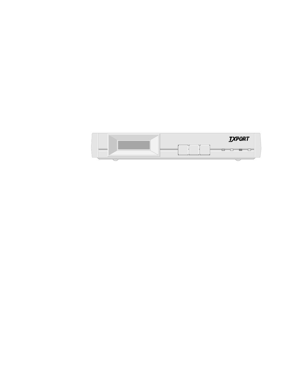
The front panel interface (Figure 3-1) allows you to configure network, port, and
SNMP parameters and troubleshoot the unit using loop tests and BERTs without
having to physically connect a terminal to the unit. The interface screen can be
manipulated using the three front panel buttons. The interface screen and the LED
indicators allow you to see the unit’s status.
Figure 3-1 PRISM 4101 Front Panel
Front Panel
LEDs
Four front panel LEDs allow a visual identification of test results and alarms.
BACKUP
This amber LED blinks when a DBU connection is being established or
terminated. It illuminates when the DBU is actively transferring data.
TEST
This amber LED illuminates when the unit is transmitting loop code, unloop code
or the 511 BERT pattern. It also illuminates when the unit is placed in a loop
mode such as line, data, V.54, etc.
ALARM
This red LED illuminates when the unit is in an active alarm condition.
POWER
This green LED illuminates when power is applied to the unit.
Front Panel
Buttons
Three buttons on the front panel allow you to select, scroll, and exit the front panel
interface menus for the unit.
Exit
This button returns you to the previous menu. Once you are at the main menu, the
Exit button closes your interface session. Modifications to some menus do not take
effect until you exit from that menu.
Scroll
This button allows you to toggle through a list of options for each menu item
selected.
SCROLL
EXIT
SELECT
BACKUP TEST ALARM POWER
PRISM 4101
T
R
A
N
S
P
O
R
T
®