4 mechatrolink-ii option components, Mechatrolink-ii option, Figure 1 – Yaskawa 1000 Series Drive Option - MECHATROLINK-II Installation User Manual
Page 10: 4mechatrolink-ii option components
Advertising
10
YASKAWA ELECTRIC
TOBP C730600 50C YASKAWA 1000-Series Option SI-T3 Installation Manual
4 MECHATROLINK-II Option Components
4
MECHATROLINK-II Option Components
◆
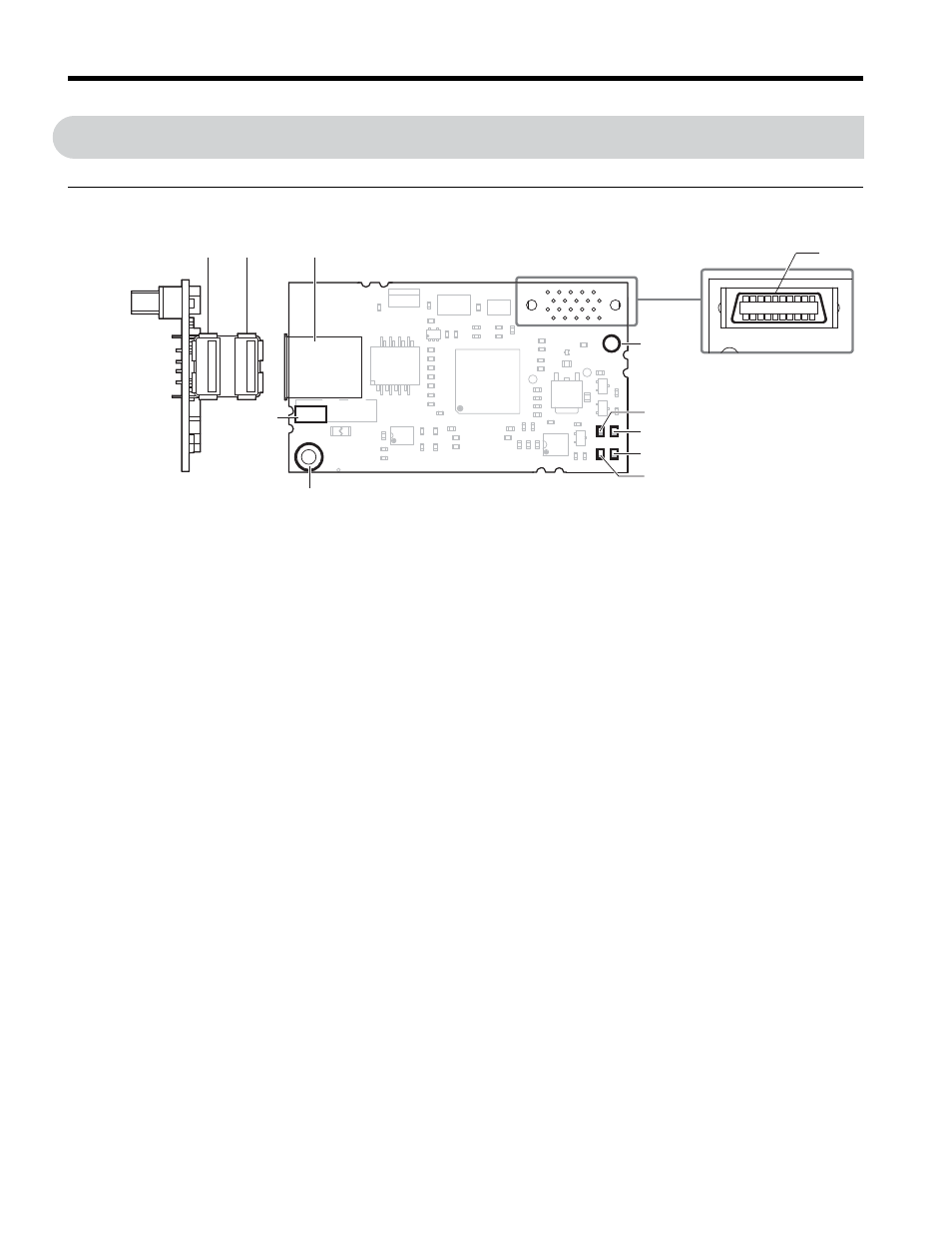
MECHATROLINK-II Option
Figure 1
Figure 1 Option
Note: For details on the LEDs, Refer to
MECHATROLINK-II Option LED Display on page 12
.
A – Connector (CN101)
G – Ground terminal (installation hole)
B – Installation hole
H – Model number
C – LED (ERR)
I – Communication cable connector (CN3)
D – LED (RUN)
J – Connector B
E – LED (TX)
K – Connector A
F – LED (RX)
Looking from the connector
Underside
SI-T3
I
J
K
H
A
B
C
G
F
E
D
Advertising
This manual is related to the following products: