Mechatrolink-ii communications cables, 5 installation procedure – Yaskawa 1000 Series Drive Option - MECHATROLINK-II Installation User Manual
Page 22
5 Installation Procedure
22
YASKAWA ELECTRIC
TOBP C730600 50C YASKAWA 1000-Series Option SI-T3 Installation Manual
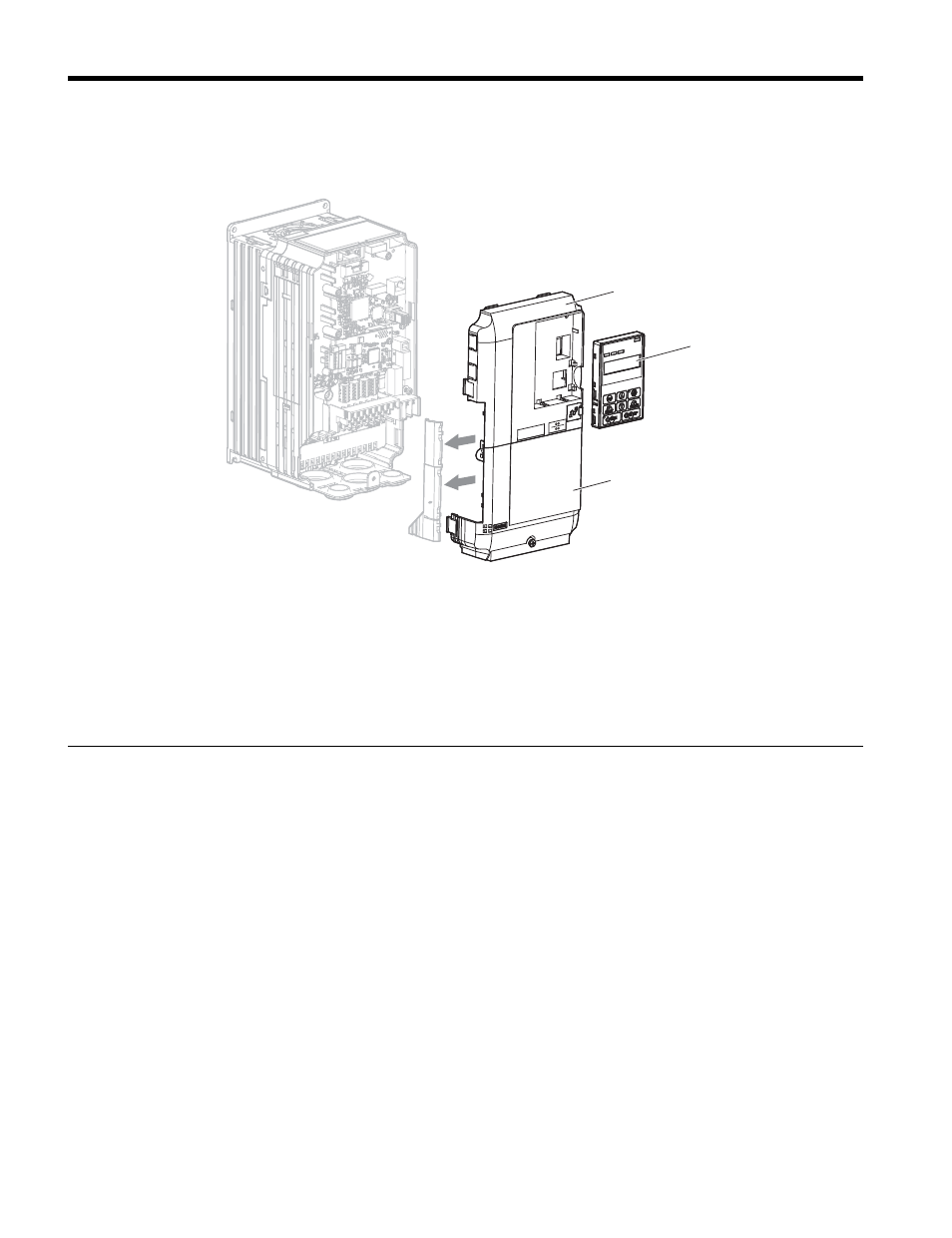
7.
Replace and secure the front covers of the unit (C, F) and replace the digital
operator (D).
Figure 10
Figure 10 Replace the Front Covers and Digital Operator
Note: Take proper precautions when wiring the option so that the front covers will easily fit back onto
the unit. Make sure no cables are pinched between the front covers and the unit when replacing
the covers.
8.
Set unit parameters in
for proper option performance.
◆
MECHATROLINK-II Communications Cables
Wire the MECHATROLINK-II communications cables to the communications connector
(CN3). Install MECHATROLINK-II communications cables apart from main-circuit wiring
and other electrical and power lines.
Note: 1. For communications cables, use special shielded twisted-pair cables for MECHATROLINK
communications.
Recommended cable: JEPMC-W6002--E
JEPMC-W6003--E (with a core)
2. Connect the terminator (model No.: JEPMC-W6022-E) on the end of the communication lines.
3. Maximum transmission distance is 50 m (1969.0 in.). Minimum wiring distance between stations is
0.5 m (19.7 in.).
<1> is the length (m).
MS
NS
F
C
D