4 option components, Pg-f3 option, Terminal blocks tb1 and tb2 – Yaskawa Option PG-F3 Motor Encoder Feedback User Manual
Page 10: Nameplate (refer to, Figure 1, For more, 4option components
Advertising
10
YASKAWA ELECTRIC TOBP C730600 51F 1000-Series Option PG-F3 Installation Manual
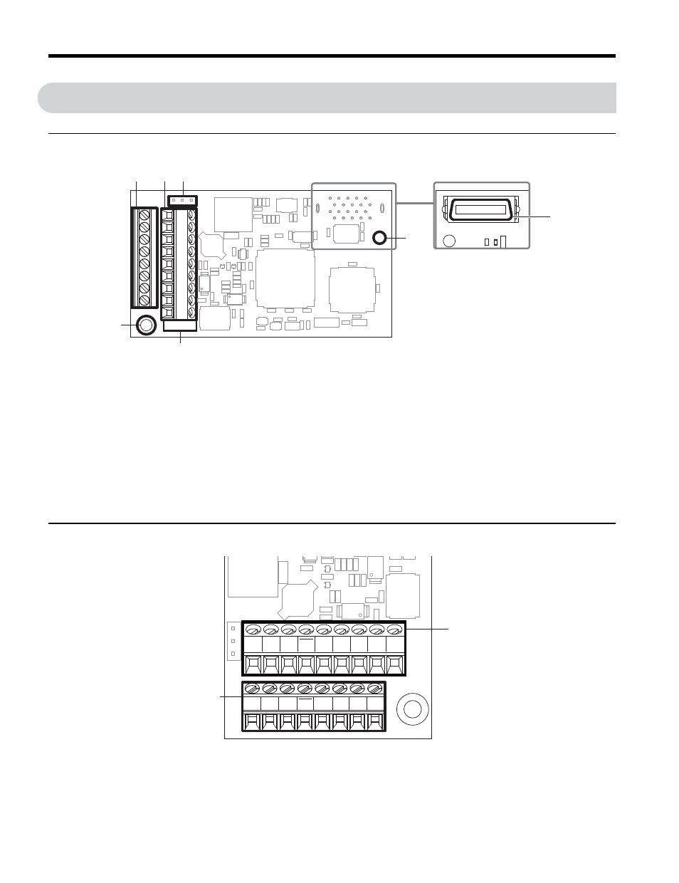
4 Option Components
4
Option Components
◆
PG-F3 Option
Figure 1
Figure 1 PG-F3 Option Components
◆
Terminal Blocks TB1 and TB2
Refer to
for details on TB1 and TB2 terminal functions and
signal levels.
A – Terminal block TB1
E – Installation hole
B – Terminal block TB2
F – Model number
C – Jumper for PG encoder power
supply voltage (CN3)
G – Ground terminal and installation
hole
<1> Refer to
on page
for details.
<2> The ground wires provided in the option shipping package must be connected during installation.
D – Connector (CN5)
G
E
A
F
C
B
D
Underside
PG-F3
CN3
F3
IP
b–
b+
B+ B–
DT
DT
IG
TB1
TB2
IP IG CK CK A+ A– a+ a– FE
F3
Advertising
This manual is related to the following products: