5 installation procedure – Yaskawa Option PG-F3 Motor Encoder Feedback User Manual
Page 23
5 Installation Procedure
YASKAWA ELECTRIC TOBP C730600 51F 1000-Series Option PG-F3 Installation Manual
23
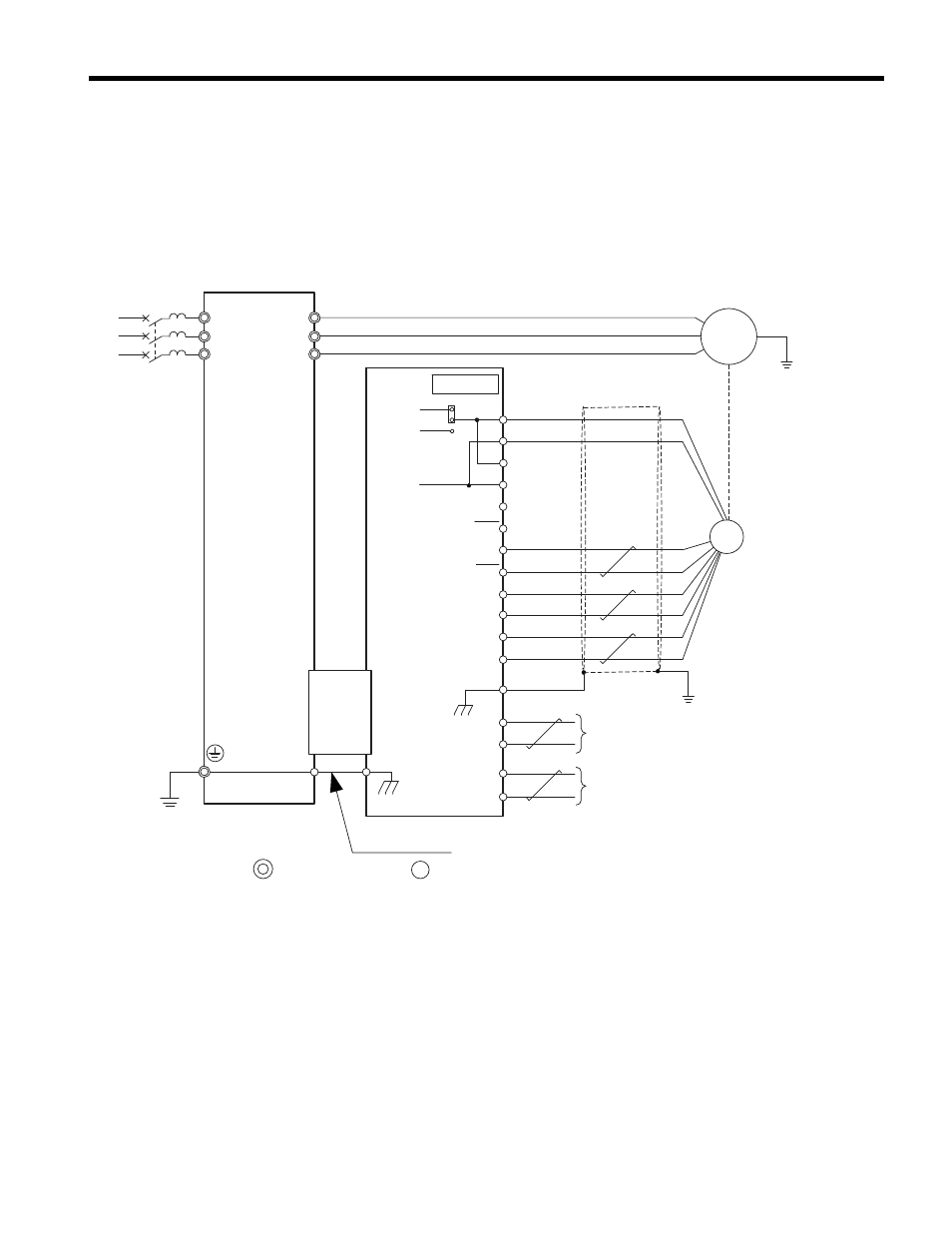
• Wiring an HIPERFACE Encoder
Wire the motor PG encoder to the terminal block on the option using a SICK
STEGMANN 8-conductor cable. Refer to
for wiring
instructions. Refer to
for the connection diagram.
Refer to Option Terminal Functions (EnDat) on page 29
for a detailed description
of the option terminal functions.
Figure 10 PG-F3 Option and PG Encoder Connection Diagram (HIPERFACE)
<1> Ground the shield on the PG encoder side and the drive side. If noise problems arise in the PG encoder signal,
remove the shield ground from one end of the signal line or remove the shield ground connection on both ends.
<1>
M
R/L1
S/L2
T/L3
U/T1
FE
TB1, TB2
V/T2
W/T3
CN3
CN5-C
B+
B–
A–
A+
DT
DT
CK
CK
IP
IP
IG
IG
FE
a+
a–
b+
b–
0V
5V
8V
Us
GND
Data–
Data+
+COS
+SIN
REFCOS
REFSIN
main circuit terminal control circuit terminal
YASKAWA
Drive
Cable
(by SICK STEGMANN)
HIPERFACE
encoder
A pulse monitor signal
B pulse monitor signal
Ground wire
F3