5 installation procedure, Figure 6, Figure 7 – Yaskawa Option PG-F3 Motor Encoder Feedback User Manual
Page 21: Figure 9
5 Installation Procedure
YASKAWA ELECTRIC TOBP C730600 51F 1000-Series Option PG-F3 Installation Manual
21
•
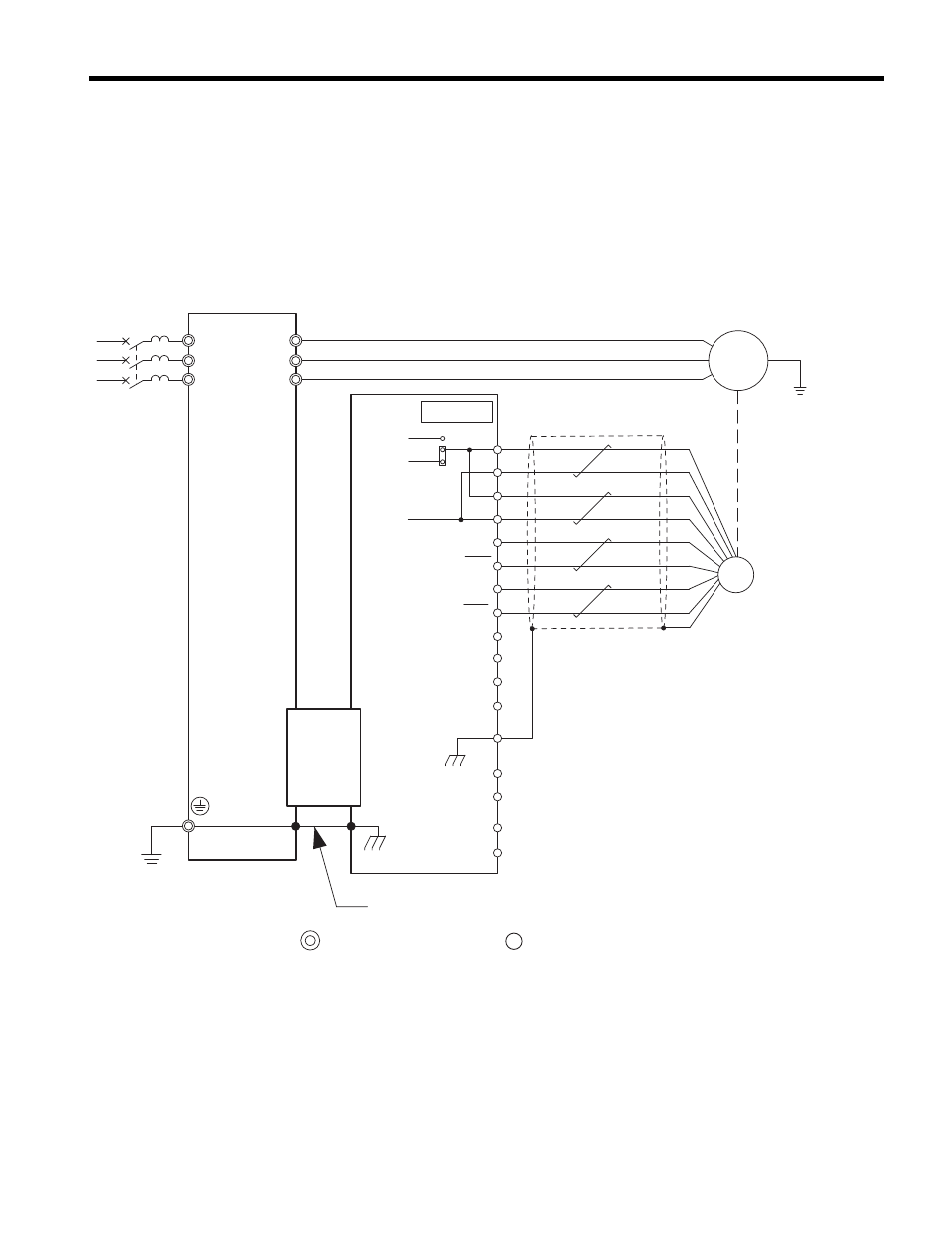
Wiring an EnDat 2.2/22 Encoder
Wire the motor PG encoder to the terminal block on the option using a HEIDENHAIN 8-
conductor cable. Refer to
and
for wiring instructions. Refer to
for the connection diagram.
The signal “Sensor Up” must be connected to terminal IP on the PG-F3 option for cables
longer than 10 m. Additionally, the “Sensor 0 V” must be connected to terminal IG.
to Option Terminal Functions (EnDat) on page 29
for a detailed description of the
option terminal functions.
Figure 9 PG-F3 Option and PG Encoder Connection Diagram (EnDat 2.2/22)
<1> Ground the shield on the PG encoder side and the drive side. If noise problems arise in the PG encoder signal,
remove the shield ground from one end of the signal line or remove the shield ground connection on both ends.
b
–
b+
a
–
a+
B
–
B+
A
–
A+
FE
DT
DT
CK
CK
IG
IP
IG
IP
CN3
TB1,TB2
PG-F3
Option
8V
5V
0V
EnDat 2.2/22
encoder
M
Cable
(by HEIDENHAIN)
U/T1
V/T2
W/T3
R/L1
S/L2
T/L3
YASKAWA
Drive
FE
CN5-C
main circuit terminal control circuit terminal
<1>
Ground wire
F3