3 devicenet communications connectors (cn6), 4 precautions for wiring devicenet cables, Connector specifications – Yaskawa AC Servo Drives Sigma II Series DeviceNet User Manual
Page 23: Connector pin arrangement, Maximum network length
E-20
4.3 DeviceNet Communications Connectors (CN6)
The terminal layout and specifications of the CN6 connectors are shown below.
Connector Specifications
The following table shows the connector specifications. These connectors are metal plated
with a flange attached.
Connector Pin Arrangement
he connector pin arrangement is as shown below.
4.4 Precautions for Wiring DeviceNet Cables
Observe the following precautions when wiring DeviceNet cables.
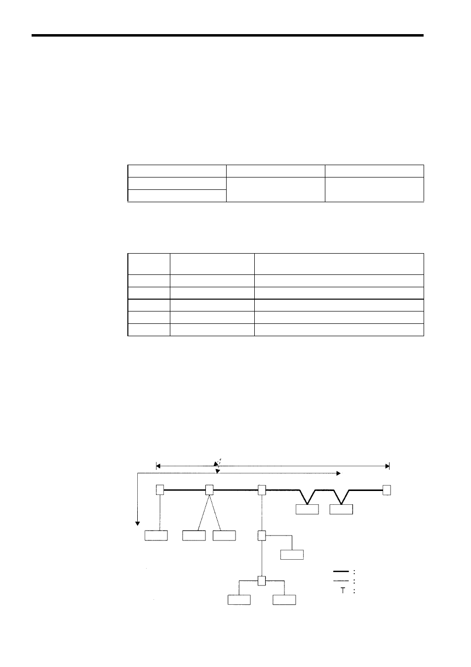
Maximum Network Length
The maximum network length is either the line length between two nodes located farthest
from each other or the line length between the terminators on the ends of the trunk line,
whichever is longer.
Name
Model
Manufacturer
Connector
MSTB2.5/5–STF–5.08AU
PHOENIX CONTACT
Case
Pin No.
and Code
Symbol
Detail
1
0 (24 V)
0 V external communications power supply
2
CAN L
CAN bus line dominant L
3
SHIELD
Connect to the wire mesh around the cable.
4
CAN H
CAN bus line dominant H
5
24 V
24 V external communications power supply
T
T
T
T
The longer of the two distances is the maximum network length.
Terminator
Trunk line
Drop line
T-Branch Adapter
Node
Node
Node
Node
Node
Node
Node
Node
T-Branch Adapter
(with terminator)