5 grounding, Important – Yaskawa AC Servo Drives Sigma II Series DeviceNet User Manual
Page 27
E-24
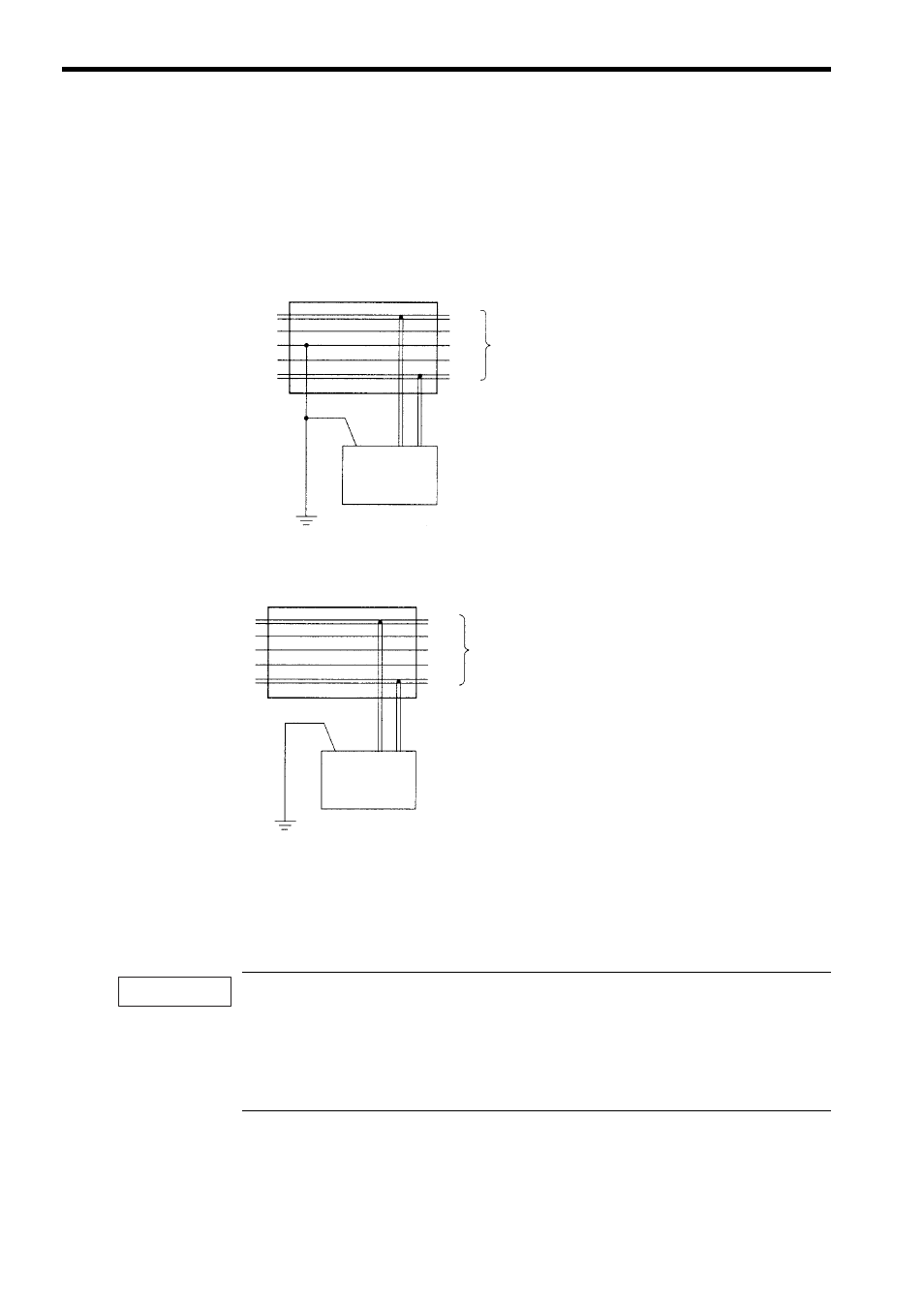
4.5 Grounding
As shown below, connect the shield wire of the cable to the FG terminal of the communica-
tions power supply and ground the shield wire to a resistance of 100
Ω or less.
Power Supply with Single-point Ground
Power Supply without Ground
If more than one communications power supply is used, ground only the power supply that
is located closest to the middle of the network through the shield wire. Do not ground the
power supply through the shield wire at any other point. If more than one communications
power supply is connected to the network, connect them using a Power Supply Tap each.
1. Power supplies are not counted as nodes.
2. Ground the network to a resistance of 100
Ω or less.
3. Do not ground the network together with servodrivers or inverters.
4. Do not ground the network through the shield wire at more than one point; ground at a single point
only.
T-Branch Adapter or Power Supply Tap
Ground to resistance of 100
Ω or less
Communication
cable
Communications
power supply
V+
CAN H
Shield
CAN L
V-
FG
V+
V-
Power Supply Tap
Communication
cable
Communications
power supply
V+
CAN H
Shield
CAN L
V-
FG
V+
V-
Ground to resistance of 100
Ω or less
IMPORTANT