Yaskawa E7 Drive Technical Manual User Manual
Page 13
Date: 02/25/2010, Rev: 10-02
Page 13 of 34
TM.F7SW.064
4.1 Parameters (continued)
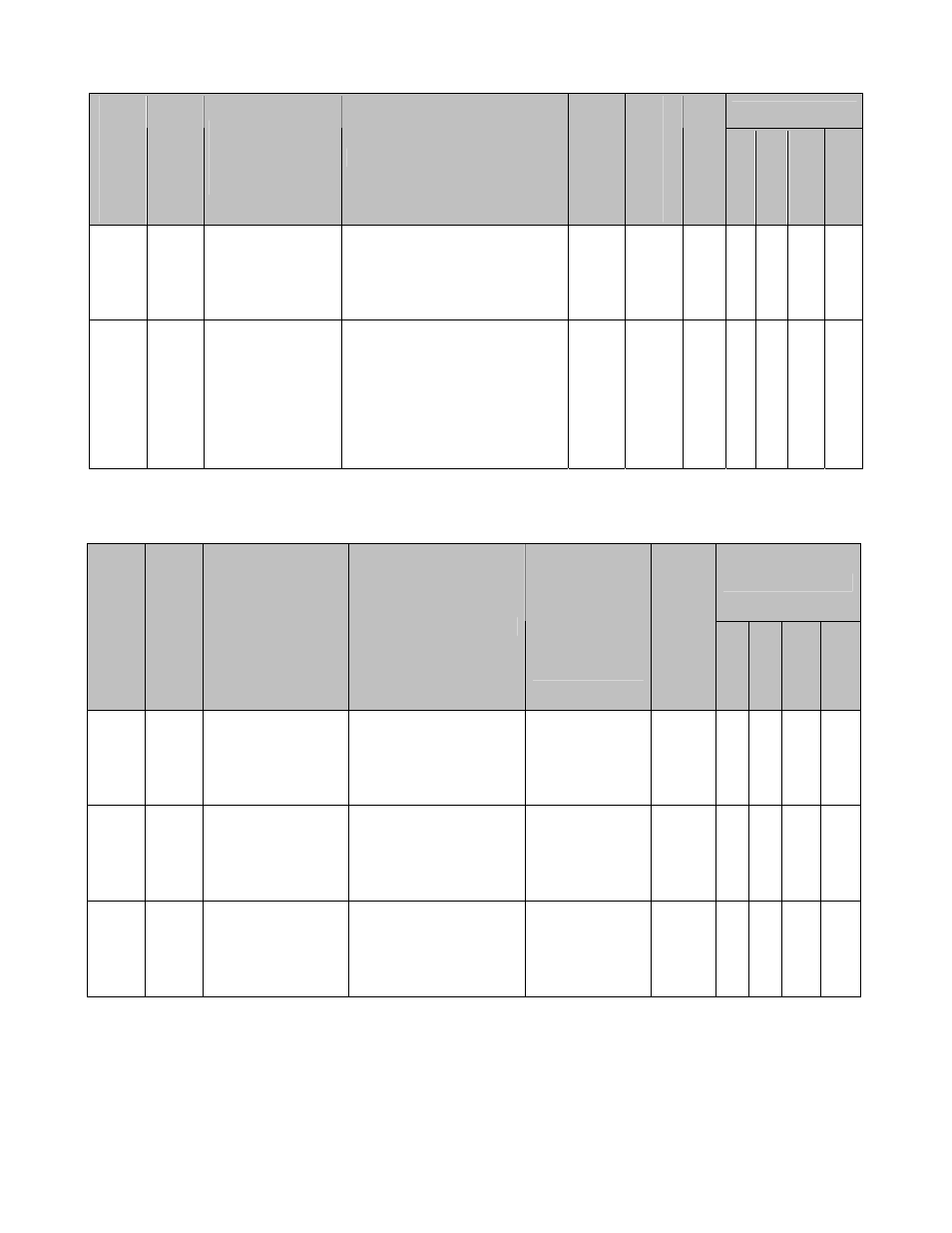
Control Mode *1
Para
meter
Numb
er
Modbus
Address
Parameter Name
Digital Operator
Display
Description
Range
Default
Cha
nge Duri
ng
Run
V/f
V/f w/
PG
Open Loop
Vector
Flux Vector
P4-07 10CH
Maximum
Alignment
Distance
Max Align Dist
Sets the maximum number of
follower motor revolutions
between the trigger inputs
before an Alignment Fault will
occur (P4-06).
1 ~
5000
rev
1000 N A A A A
P4-08 10DH
Maximum
Alignment Speed
Max Align Speed
Sets the maximum follower
speed that will be allowed for
an alignment to occur. This
can be used to prevent
alignment at high speeds
where accuracy is diminished.
A setting of 0.0 Hz disables
this function.
0.0 ~
400.0
Hz
0.0 Y
A
A
A A
*1: Access Level (A1-01): Q = “Quick Start”, A = “Advanced”, F = “Factory”.
4.2 Monitors (U1-XX)
Control Mode *1
Monitor Num
ber
Modbu
s A
dd
re
ss
Monitor Name
Digital Operator
Display
Description
Scaling for
Multi-function
Analog Output
Terminals
FM and AM
(H4-01, H4-04)
Unit
V/f
V/f w/
PG
Open
Loop
Vector
Flux Vector
U1-90 720H
Master Encoder
Reference
Master PG Fref
Displays the frequency
of the master encoder
before gear ratios and
MOP gains are
applied.
100% =
Maximum
Output
Frequency
(E1-04)
0.1
Hz
Q Q Q Q
U1-91 721H
Follower
Reference After
Gear Ratio
Fref After Gear
Displays the frequency
of the master encoder
after the active gear
ratio (P1-03 ~ P1-08)
is applied.
100% =
Maximum
Output
Frequency
(E1-04)
0.1
Hz
Q Q Q Q
U1-92 722H
Gear Ratio
Adjustment
Gear Ratio Adj
Displays the total gear
ration adjustment (sum
of digital, analog, MOP
and communication
adjustments).
100% =
100.00%
0.01% Q Q Q Q
*1: Access Level (A1-01): Q = “Quick Start”, A = “Advanced”, F = “Factory”.