Yaskawa E7 Drive Technical Manual User Manual
Page 5
Date: 02/25/2010, Rev: 10-02
Page 5 of 34
TM.F7SW.064
2.0 Changes from Standard Product
a. The Motor 2 Selection (H1-0X = 16) multi-function digital input function is deleted (only Motor 1 can be
used).
b. The kWh monitors (U1-29 and U1-30) are deleted.
c. Parameter E2-04 (Motor Poles) is available in all control modes (Advanced access level only for V/f and
Open Loop Vector).
d. The follower drive uses acceleration and deceleration times of zero during standard Electronic Line Shaft
(P1-01 = 4, 5).
e. All “A2” parameters along with the entire user access level have been deleted from this software.
3.0 Limitations
a. For ELS modes (P1-01 = 4, 5), Flux Vector control mode is highly recommended (A1-02 = 3).
b. For ELS modes (P1-01 = 4, 5), the gear ratio must be exactly expressed, including remainder, to prevent
phase drift (error). See section 5.0.
c. The proper encoder (PG) option card must be used based on the control mode and follower mode
selection. The table below shows the supported option cards for each configuration.
d. If the “Clear Position Error” digital input is activated when an alignment is being performed, the drive could
possibly experience a step-change in frequency reference.
e. Alignment accuracy will be lessened at higher speeds. This is due to latency in the trigger
switches themselves and the drive’s digital inputs and internal scan rate.
Encoder (PG) Option Card Selection
Control Mode
P1-01 = 1, 2, 3 (Speed Follower)
P1-01 = 4, 5 (ELS)
V/f
PG-B2, PG-T2, PG-X2, PG-W2, PG-Y2, PG-Z2
V/f w/ PG
PG-W2, PG-Y2, PG-Z2
Open Loop Vector
PG-B2, PG-T2, PG-X2, PG-W2, PG-Y2, PG-Z2
Flux Vector
PG-W2, PG-Y2, PG-Z2
PG-W2, PG-Y2, PG-Z2
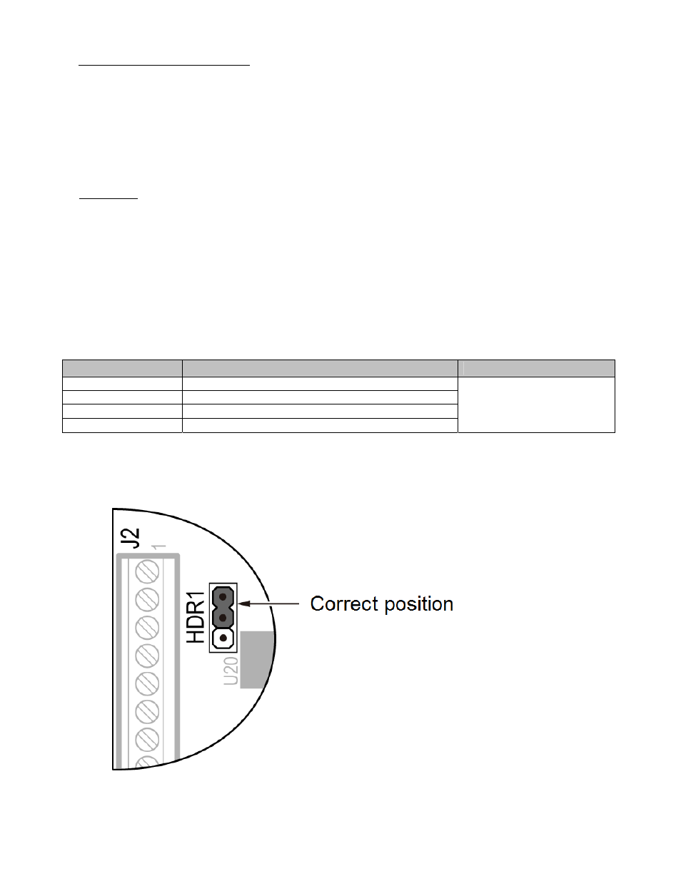
Note: If the PG-W2 option is used, jumper HDR1 must be set to the correct position
according to the figure below.