Yaskawa E7 Drive Technical Manual User Manual
Page 15
Date: 02/25/2010, Rev: 10-02
Page 15 of 34
TM.F7SW.064
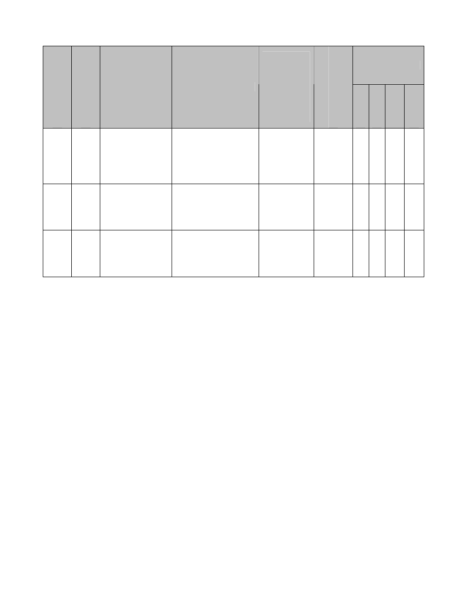
4.2 Monitors (U1-XX) (continued)
Control Mode *1
Monitor Num
ber
Modbu
s A
dd
re
ss
Monitor Name
Digital Operator
Display
Description
Scaling for
Multi-function
Analog
Output
Terminals
FM and AM
(H4-01, H4-
04)
Unit
V/f
V/f w/
PG
Open
Loop
Vector
Flux Vector
U1-97 727H
Position Regulator
P Output
Position P Out
Displays the
proportional gain
contribution of the
position PI regulator.
Note: ELS modes only.
100% =
Maximum
Output
Frequency
(E1-04)
0.01% Q Q Q Q
U1-98 728H
Position Regulator
I Output
Position I Out
Displays the output of
the integrator of the
position PI regulator.
Note: ELS modes only.
100% =
Maximum
Output
Frequency
(E1-04)
0.01% Q Q Q Q
U1-99 729H
Position Regulator
PI Output
Position PI Out
Displays the output of
the position PI
regulator.
Note: ELS modes only.
100% =
Maximum
Output
Frequency
(E1-04)
0.01% Q Q Q Q
*1: Access Level (A1-01): Q = “Quick Start”, A = “Advanced”, F = “Factory”.