Composite gear ratio diagram – Yaskawa E7 Drive Technical Manual User Manual
Page 34
Advertising
Date: 02/25/2
010, Rev: 10
-02
Page 34 of 3
4
TM.F7SW.06
4
6.0
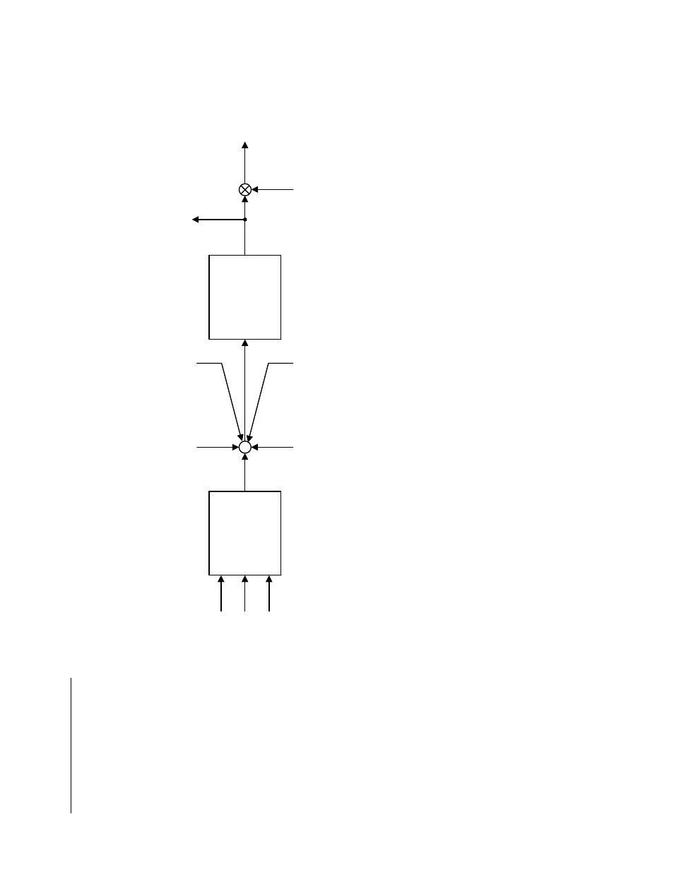
Block Dia
grams (continued)
MO
P
Ad
ju
st
m
en
t
M
O
P In
cr
ea
se
(
H
1-
X
X
=
8
4)
M
O
P
D
ec
rea
se
(
H
1-
X
X
= 85
)
M
O
P
R
ese
t (
H
1-
X
X
=
8
6)
Di
gi
ta
l Ra
tio
Ad
ju
st
m
en
t
(P
2-0
1)
A
nal
og
Rat
io
Ad
ju
st
m
en
t
H3-
05
/09
= 20
N
etw
or
k C
om
m
un
ica
tio
n
Rat
io A
dj
us
tm
en
t
(M
od
bu
s Re
gi
st
er 6
1C
H
)
10
0%
+
+
+
+
+
Gea
r Ra
tio
A
dj
ustm
en
t
(U
1-9
2)
G
ea
r R
ati
o
Ad
ju
stm
en
t
R
amp
T
ime
(P2-
03
)
F
ol
low
er
R
efe
re
nc
e Afte
r
G
ea
r R
ati
o
(U1-
91
)
Follow
er
R
efe
re
nc
e Afte
r
G
ea
r R
ati
o
Ad
ju
stm
en
t
(U
1-9
3)
Composite Gear Ratio Diagram
Advertising
This manual is related to the following products: