Output voltage waveform – Yaskawa GPD 506/P5 Section Two User Manual
Page 14
Advertising
PP.P5G5.02Troubleshoot
Page 14
Rev. 06/11/2003
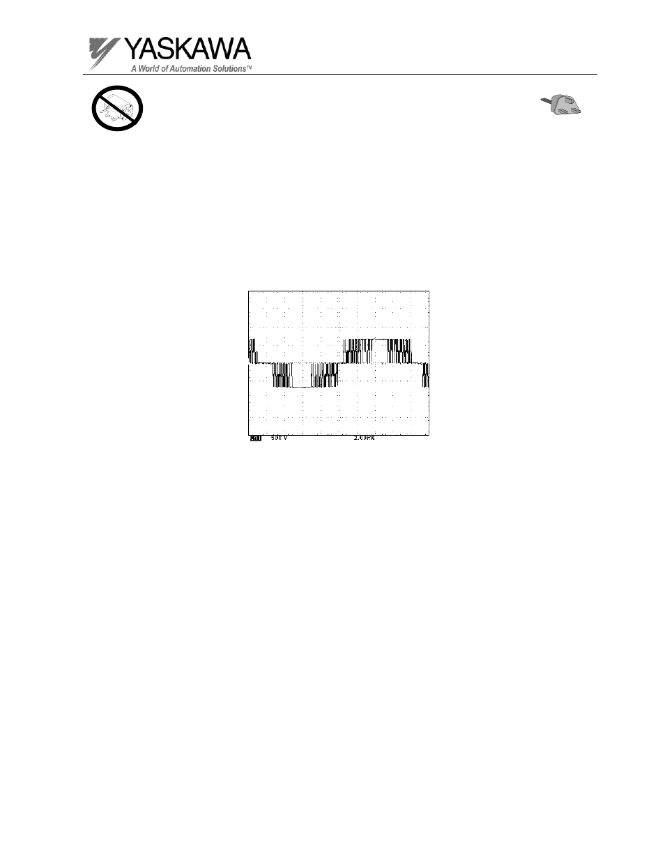
Output Voltage Waveform
Step 7
Test Equipment - Ungrounded oscilloscope with X 100 probe
Set scope to 500V/division and 2mSeconds, in order to observe the output voltage waveform.
Before attempting to run the inverter, make a list of all the parameters that have been
changed from the factory settings. Initialize the drive and set it up to accept a run command
and frequency reference from the digital operator.
1. Using the oscilloscope, measure between T1 and T2.
2. Run the inverter up to 60 Hz, watching the waveform as it accelerates.
3. Compare the waveform with the waveform shown below.
4. Stop the inverter.
5. Repeat steps 1 through 4 measuring T1 to T3 and T2 to T3.
Advertising
This manual is related to the following products: