Gate circuit check – Yaskawa GPD 506/P5 Section Two User Manual
Page 17
PP.P5G5.02Troubleshoot
Page 17
Rev. 06/11/2003
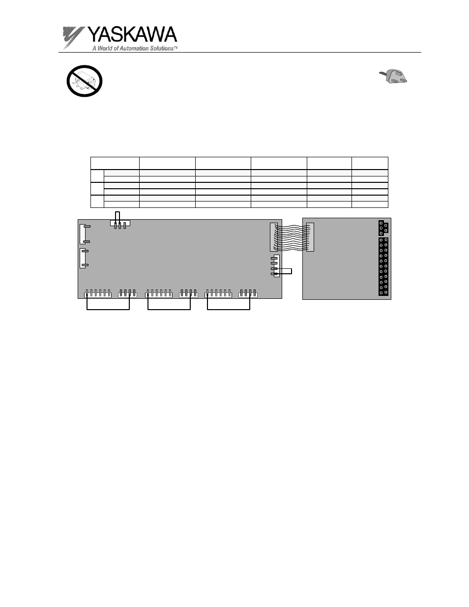
Step 8
Test Equipment - Ungrounded oscilloscope with X 10 probe, DC Voltmeter, jumper wires.
1. Making sure that the power is not applied to the inverter, and the DC Bus
voltage is below 10V, remove the gate drive board and the control board.
2. Using the following chart, attach jumper wires to the gate drive board or a fault will
occur.
Gate Circuit Check
Gate drive board
ETC61509X
11Cn
12Cn
13Cn
14Cn
15Cn
16Cn
17Cn
25Cn
6 5 4 3 2 1
4 3 2 1
6 5 4 3 2 1
4 3 2 1
6 5 4 3 2 1
4 3 2 1
3 2 1
1
3
27Cn
4 3 2 1
Gate drive board for 230V 37kW
7Cn
7Cn
Control board
ETC61599X-SXXXX
♣
♣
18kW does not have an answer back.
Jumper #1
Jumper #2
Jumper #3
Jumper #4
Jumper #5
Size
(for Short Circuit)
(for Short Circuit)
(for Short Circuit)
(for answer back)
(for fan fault)
230V 18kW, 22kW
16CN pin 2 to 6
17CN pin 2 to 6
18CN pin 2 to 6
11CN pin 1 to 2
12CN pin 2 to 3
30kW ~ 75kW
15CN pin 6 to 16CN pin 2 13CN pin 6 to 14CN pin 2 11CN pin 6 to 12CN pin 2
27CN pin 3 to 4
17CN pin 2 to 3
460V 18kW ~ 45kW
16CN pin 2 to 6
17CN pin 2 to 6
18CN pin 2 to 6
11CN pin 1 to 2
12CN pin 2 to 3
55kW ~ 160kW 15CN pin 6 to 16CN pin 2 13CN pin 6 to 14CN pin 2 11CN pin 6 to 12CN pin 2
27CN pin 3 to 4
17CN pin 2 to 3
600V 18kW ~ 22kW
15CN pin 4 to 16CN pin 2 13CN pin 4 to 14CN pin 2 11CN pin 4 to 12CN pin 2
not required
not required
30kW ~ 160kW 15CN pin 4 to 16CN pin 2 13CN pin 4 to 14CN pin 2 11CN pin 4 to 12CN pin 2
23CN pin 3 to 4
not required
26Cn
1
5
♣