Gate circuit check, 325 v, The table below is for a through c spec boards – Yaskawa GPD 506/P5 Section Two User Manual
Page 18
PP.P5G5.02Troubleshoot
Page 18
Rev. 06/11/2003
The table below is for A through C spec boards.
Step 8
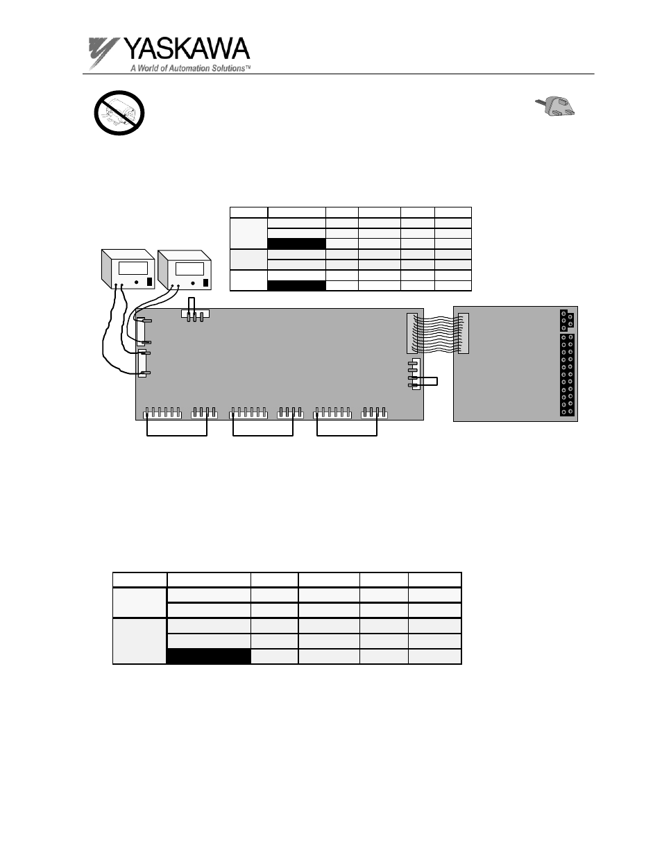
Test Equipment - Ungrounded oscilloscope with X 10 probe, DC Voltmeter, jumper wires.
3. Apply power to the gate drive board using the following chart.
Gate Circuit Check
DC Power
Supplies
Gate drive board
ETC61510X
11Cn
12Cn
13Cn
14Cn
15Cn
16Cn
17Cn
25Cn
3 2 1
1
3
27Cn
4 3
2 1
Gate drive board for 230V 37kW
7Cn
7Cn
325
V
- +
Size
Voltage Connector Positive Negative
18kW, 22kW
325VDC
19CN
pin 5
pin 1
230V
30kW ~ 75kW
325VDC
25CN
pin 1
pin 3
325VDC
26CN
pin 1
pin 5
460V
18kW ~ 45kW
650VDC
19CN
pin 5
pin 1
55kW ~ 160kW 650VDC
26CN
pin 5
pin 1
575V
18kW ~ 160kW 845VDC
22CN
pin 1
pin 4
325VDC
21CN
pin 1
pin 3
1
5
26Cn
Control board
ETC61599X-SXXXX
325
V
- +
6 5 4 3 2 1
4 3 2 1
6 5 4 3 2 1
4 3 2 1
6 5 4 3 2 1
4 3 2 1
Size
Voltage Connector Positive Negative
230V
18kW, 22kW
325VDC
19CN
pin 5
pin 1
30kW ~ 75kW
325VDC
25CN
pin 1
pin 3
18kW ~ 45kW
650VDC
19CN
pin 5
pin 1
460V
55kW ~ 160kW 325VDC
25CN
pin 1
pin 3
650VDC
26CN
pin 1
pin 5