Gate circuit check – Yaskawa GPD 506/P5 Section Two User Manual
Page 16
Advertising
PP.P5G5.02Troubleshoot
Page 16
Rev. 06/11/2003
Gate Circuit Check
for models 18kW through 160kW
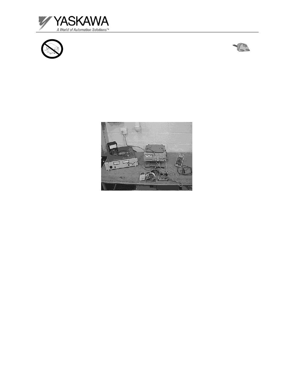
Step 8 (Only perform this test if the Output waveform is not working properly)
When an output transistor has been replaced, the firing circuit on the gate
drive board should be tested. With the gate drive board mounted inside the
inverter, it is difficult to access the test points to thoroughly test the gate
firing circuit. It is recommended that the gate drive board and the control
board be removed from the inverter and tested on a test bench.
• Never power up the inverter with the gate wires removed or the
IGBT(s) will be damaged!
Advertising
This manual is related to the following products: