Gate circuit check – Yaskawa GPD 506/P5 Section Two User Manual
Page 15
Advertising
PP.P5G5.02Troubleshoot
Page 15
Rev. 06/11/2003
Gate Circuit Check
for models 0.4kw through 15kW
Step 8 (Only perform this test if the Output waveform is not working properly)
Test Equipment - Ungrounded oscilloscope with X 10 probe
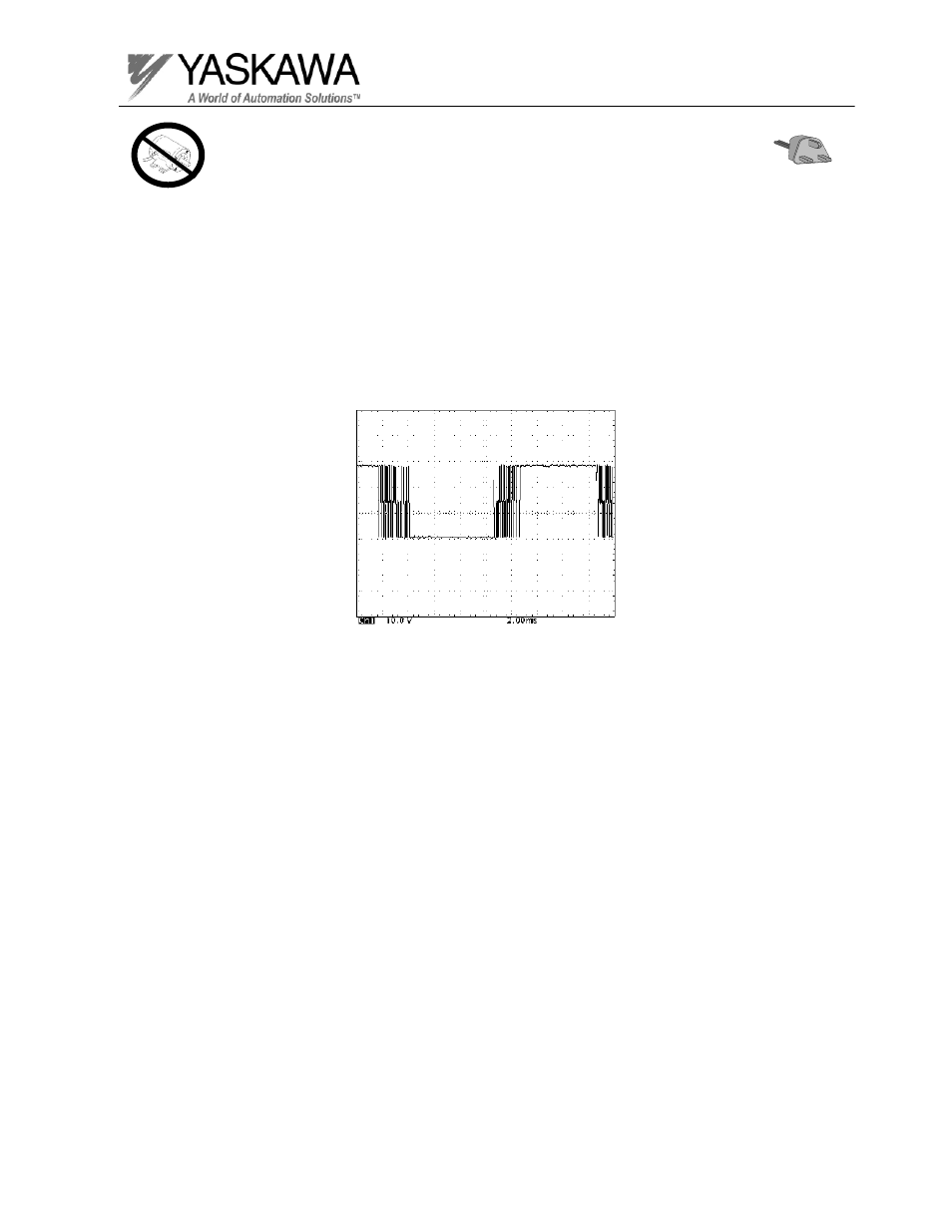
Set scope to 10V/division and 2mSeconds, in order to observe the gate firing pulses.
1. Using the oscilloscope, measure between the gate and emitter pins which lead
to the output IGBT.
2. Run the inverter at 60HZ, and compare the waveform you see with the one
shown below.
3. Stop the inverter.
4. Repeat steps 1 through 3 measuring all six gate pulses.
• Never power up the inverter with the Gate wires removed or the IGBT will be
damaged!
Advertising
This manual is related to the following products: