Rear panel – Rose Electronics ClassView User Manual
Page 9
Advertising
REAR PANEL
CLASSVIEW INSTALLATION AND OPERATINS MANUAL
5
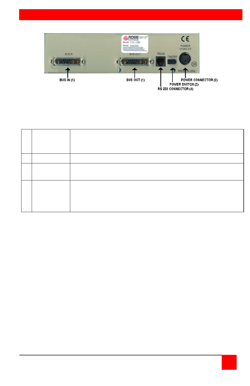
Figure 3. Rear panel, model #CVT-CMB
1
BUS in/
BUS out
Bus cable to next unit or terminator is connected here.
Terminator or bus cable may be connected to either bus in or
bus out.
2 RS232
RS232 serial port for factory diagnostics only.
3
Power
switch
Pressing the switch turns the unit on, provided supplied
power transformer is properly connected.
4 Power
Power transformer included in package connects here. This
is not a keyboard input. Power transformers are available for
U.S or International use. Input voltage is 17VAC with center
tap.
Table 2. The rear panel
Advertising