Whelen 7098000 User Manual
Aviation
Page 1
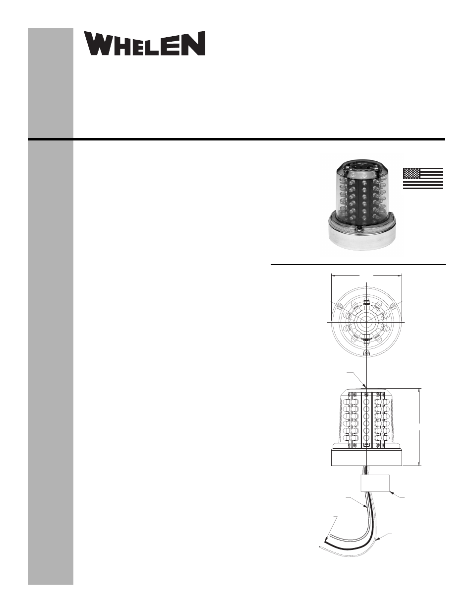
3.66
TEFLON TUBE 18GA
18"±1"LG
(PRESSURE VENTING
USED ON -00 ASSY)
(+) 28VDC WHITE 18GA
TEFLON WIRE 18"±1"LG
4.04±.06
(-)GROUND BLACK 18GA
TEFLON WIRE 18"±1"LG
MFG
LABEL
DRAIN HOLE
USED ON -01 ASSY
Installation Guide:
Model 70980( )-series
Model 7098000
P/N:01-0770980-00
01-0770980-01
Infra-Red LED Flashing Light Assembly
©2004 Whelen Engineering Company Inc.
Form No.13920A (010714)
OPERATING INSTRUCTIONS:
Operational Voltage: . . . . . . . . .28 VDC (Nominal)
Average Input Current: . . . . . . .0.1 Amps
Peak Input Current: . . . . . . . . . .0.63 Amps @ .25 Seconds
INSTALLATION PROCEDURES: The following
information is to assist in the installation of a Whelen IR
LED Light System.
1.
The installation procedure described in the following
text will be confined to a single light installation, but is
identical for multiple light installations.
2.
Using the “suggested mounting hole pattern” prepare
the aircraft for means to secure the IR LED Flashing
Light assembly.
3.
Connect the light inputs according to the chart shown.
Conect the power lead to an appropriately sized
breaker. Connections to be in accordance with FAA
approved methods. Insure that the wire leads and the
pressure venting tube are all clear of any obstructions
and secure as required. The pressure venting tube
may be trimmed to minimum length of 1” from base.
4.
Remove and discard the 3 screws from the lens
retainer. Remove the retainer and lens. CAUTION!
Do not touch the LEDs with either fingers or sharp
objects. This could soil and/or damage the LED and
effect the optical performance of the LEDs. Insert the
appropriate hardware through the counter-bored
holes and secure the assembly. Reinstall the gasket,
lens and retainer. Confirm proper gasket fit. Install the
nylon patch lens screws with 5-7 in./lbs. torque.
5.
Check all avionics systems for interference from this
installation.
6.
A flight check should be performed by a properly
certified pilot.
7.
All inverted (bottom) mounted units shall require
waterproofing of the mounting hardware. An
application of single-part silicone (RTV) or equivalent
applied over top of the mounting hardware, after
installation, is recommended. Reference page 2 for
an illustration. Inverted and/or standard mounted
units, when necessary, may require waterproofing
around any open area where water could get in.
Specifically, the lens to the flasher base assembly,
and the flasher base assembly to the aircraft.
8.
Update aircraft records, complete Form 337 and
obtain FAA field approval for installation, if necessary.
MADE IN THE U.S.A.
®
ENGINEERING COMPANY INC.
51 Winthrop Road
Chester, Connecticut 06412-0684
Phone: (860) 526-9504
Fax: (860) 526-2009
Internet: www.whelen.com
Sales/Service e-mail: [email protected]
Aviation