Whelen 7090505 User Manual
Aviation, Engineering company inc
Page 1
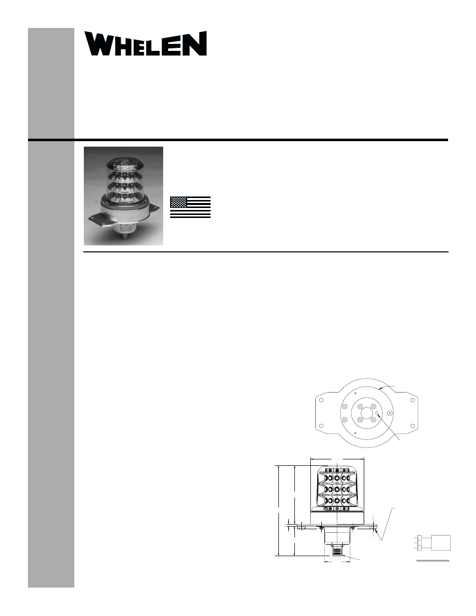
4.04 ±.06
2.05
0.125
6.22 ±.06
3.66
BOTTOM VIEW
1.75
CONN. HOUSING
2.88 DIA. .032 THICK
.156 THRU
(VENT)
MTG GASKET
(REF)
LED
MODULE
+28VDC
WIRING DIAGRAM
A
B
C
GND
N/C
CONNECTOR
MIL-C-38999 SERIES III
20FA98PN
®
ENGINEERING COMPANY INC.
Route 145, Winthrop Road,
Chester, Connecticut 06412
Phone: (860) 526-9504
Fax: (860) 526-2009
Internet: www.whelen.com
Sales/Service e-mail: [email protected]
Aviation
Installation Guide:
Model 70905( )-series
Model 7090505
P/N:01-0770905-05
LED Flashing Anti-Collision
Light Assembly
©2004 Whelen Engineering Company Inc.
Form No.13951A (080305)
OPERATING INSTRUCTIONS:
Operational Voltage: . . . . . 28 VDC
Average Input Current: . . . 0.45 Amps
Peak Input Current: . . . . . . 2.5 Amps @ .25 Seconds
EQUIPMENT LIMITATIONS:
Rotorcraft for which type certificate was applied for after April
1, 1957 to August 11,1971:
The anti-collision system must produce a minimum of 100 effective
candelas in Aviation Red or White, 360° around the vertical axis,
30° above and below the horizontal plane. A single beacon will
meet this requirement.
Rotorcraft for which type certificate was applied for after
August 11, 1971 to February 5, 1976:
The anti-collision system must produce a minimum of 400 effective
candelas in Aviation Red or White, 360° around the vertical axis,
30° above and below the horizontal plane. This beacon does not
meet this requirement.
Rotorcraft for which type certificate was applied for after
February 5, 1976:
The anti-collision system must produce a minimum of 150 effective
candelas in Aviation Red, 360° around the vertical axis, 30° above
and below the horizontal plane. A single beacon will meet this
requirement.
CONTINUED AIRWORTHINESS: The 70905 series LED anti-
collision light assembly is designed with 10 vertical columns
consisting of 3 LEDs each. Should any one LED or any vertical
column fail, the unit must be repaired or replaced.
INSTALLATION PROCEDURES: The following information is to
assist in the installation of a Whelen LED Flashing Anti-collision
Light System.
1.
The installation procedure described in the following text will
be confined to a single light installation, but is identical for
multiple light installations.
2.
Prepare the aircraft for means to secure the LED Flashing
Anti-collision Light assembly (see reference AC 43.13-2A
Chapter 4)
3.
28 VDC (+) and (-) ground leads equipped with an
appropriate sized breaker to be supplied to the LED Flashing
Anti-collision Light Assembly System. Both leads must be
connected by an approved FAA connection. Insure that the
wire leads are all clear of any obstructions and ty-wrap as
required.
TSO-C96a CLASS I
APPROVED
MADE IN THE U.S.A.
The conditions and tests required for TSO approval of this
article are minimum performance standards. It is the
responsibility of those installing this article either on or
within a specific type or class of aircraft to determine that
the aircraft installation conditions are within the TSO
standards. TSO articles must have separate approval for
installation in aircraft. The article may be installed only if
performed under 14 CFR part 43 or the applicable
airworthiness requirements.
4.
Install the light assembly by securing to aircraft using the
appropriate, approved hardware. Note: Lens mounting screws
installed with 5-7 in./lbs. of torque.
5.
Check all avionics systems for interference from this installation.
6.
A flight check should be performed by a properly certified pilot.
7.
All inverted (bottom) mounted units shall require waterproofing of
the mounting hardware. An application of single-part silicone (RTV)
or equivalent applied over top of the mounting hardware, after
installation, is recommended. Reference page 2 for an illustration.
Inverted and/or standard mounted units, when necessary, may
require waterproofing around any open area where water could get
in. Specifically, the lens to the flasher base assembly, and the
flasher base assembly to the aircraft. Note: It is permissable to drill
a 1/8” drain hole in the center of the lens for bottom mounted units.
8.
Update aircraft records, complete Form 337 and obtain FAA field
approval for installation.