Whelen 9008811 User Manual
Aviation, Installation guide, Engineering company inc
Page 1
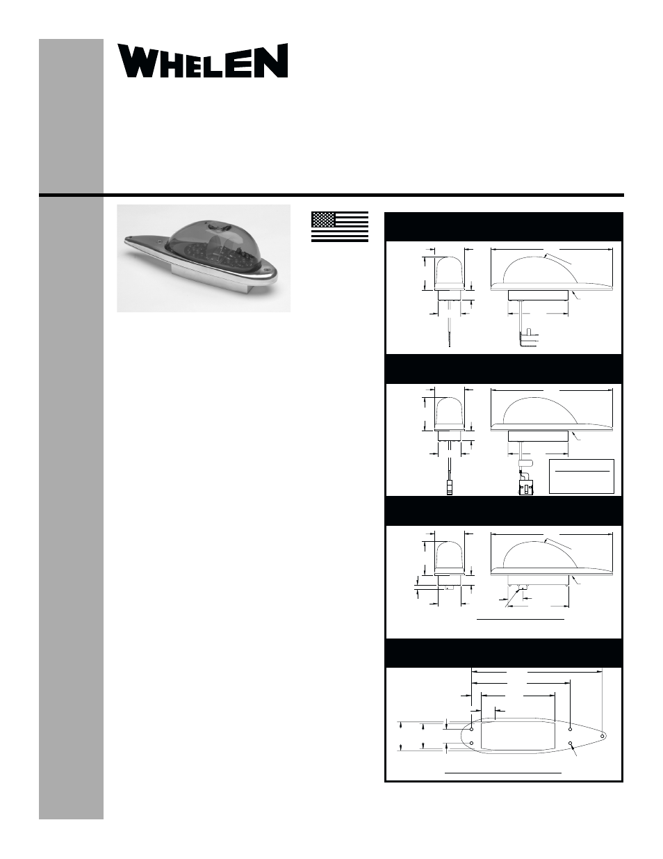
.670
.936
1.70
1.95
.90 TYP
8.880
6.700
5.00
.203 DIA.
MNTG HOLES
(5 PLACES)
SUGGESTED MOUNTING PATTERN
2.70
2.70
2.70
.38
1.84
1.84
1.84
2.38
2.38
2.38
.80
.80
.80
9.87
9.87
9.87
18.00"±1.00"
2/C Shielded Cable
#M27500-20TE2T14
8.00"±.50"
2/C Shielded Cable
#M27500-20TE2T14
4.86
4.86
WHITE - (-)GROUND
WHITE/BLUE - (+28 VDC)
SHIELD
Drain Hole
(Models -12
& -14)
Drain Hole
Drain Hole
6
(-1 Model)
Drain Hole
(Model -11)
Drain Hole
(-15 Model)
POS 1 - WHT/BLUE - +28V
POS 2 - WHITE - GND
POS 3 - SHIELD
POS 4 - N/C
AMP #1-480703-0
Connector Wiring
BRAID SHIELD
WHT - GROUND
WHT/BLUE - +28V
Receptacle - MS27508E10A-5P
POS B - GROUND
POS A - +28VDC
POS D - N/C
POS C - N/C POS E - N/C
1.20
4.86
1
2
3 4
01-0790088-11, 01-0790088-12, 01-0790088-14
01-0790088-13
01-0790088-15, 01-0790088-16
All
Model(s):
Model(s):
Model(s):
Model(s):
OPERATING INSTRUCTIONS:
Operational Voltage: . . . . . . 28 VDC (nominal)
Average Input Current: . . . . 0.56 Amps / 3 Amps Peak @ .25 Sec.
The conditions and tests required for TSO approval of this article
are minimum performance standards. It is the responsibility of
those installing this article either on or within a specific type or
class of aircraft to determine that the aircraft installation
conditions are within the TSO standards. TSO articles must have
separate approval for installation in aircraft. The article may be
installed only if performed under 14 CFR part 43 or the applicable
airworthiness requirements.
CONTINUED AIRWORTHINESS: The 90088 series led anti-collision
light assembly is designed with 2 banks of 7 leds. Should any one led or
bank fail, the unit must be repaired or replaced. Inspect the lens for
excessive scratches or pitting. Replace if necessary.
EQUIPMENT LIMITATIONS: The Class
i
III anti-collision system must
produce a minimum of 100 effective candelas in aviation red or white,
360° around the vertical axis. A single beacon on the topside of the
fuselage and a single beacon on the underside of the fuselage will meet
this requirement.
INSTALLATION PROCEDURES: The following information is to assist
in the installation of a Whelen LED Anti-Collision Light Assembly.
1.
Choose the appropriate 90088( ) replacement light assembly
which is most applicable to your aircraft. Lower mounts have a
drain hole in the lens.
2.
The installation procedure described in the following text will be
confined to a single light installation, but is identical for multiple
light installations.
3.
Remove old light, locate and save the existing +28VDC lead and
(-) ground lead. Clean and prep lead ends as required.
4.
Use existing mounting holes and hardware.
5.
Connect the +28 VDC and (-) ground leads equipped with an
appropriate sized breaker to the LED Light. Both leads must be
connected by an approved FAA connection.
6.
Install light assembly and insure that the wire leads are clear of
any obstructions and ty-wrap as required. Use lock washers and/
or thread lock on all threaded fasteners.
7.
Check all avionics systems for interference from the installation.
8.
A flight check should be performed by a properly certified pilot.
9.
Update aircraft records, complete Form 337 and obtain FAA field
approval for installation.
Installation Guide:
Model 90088( )-series
Models 9008811, 9008812, 9008813,
9008814, 9008815, 9008816
P/N:01-0790088-11, 01-0790088-12,
01-0790088-13, 01-0790088-14
01-0790088-15, 01-0790088-16
LED Anti-Collision Light Assembly
Aviation
©2005 Whelen Engineering Company Inc.
Form No.14002B (060606)
®
ENGINEERING COMPANY INC.
Route 145, Winthrop Road,
Chester, Connecticut 06412
Phone: (860) 526-9504
Fax: (860) 526-2009
Internet: www.whelen.com
Sales/Service e-mail: [email protected]
MADE IN THE U.S.A.
TSO-C96a
CLASS III
APPROVED