Whelen 7094601 User Manual
Aviation
Page 1
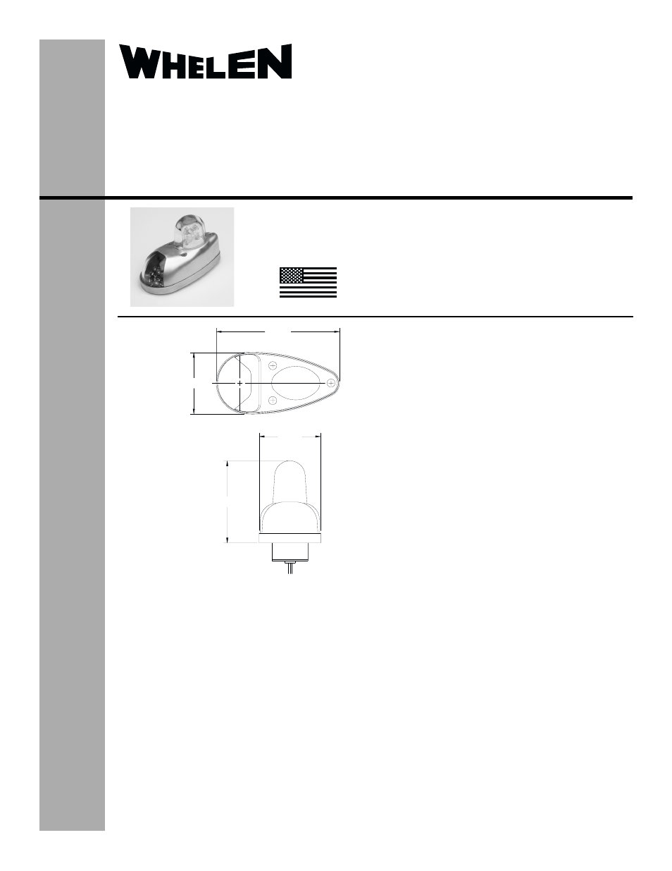
2.85
4.25
2.12
2.12
The conditions and tests required for TSO approval of this
article are minimum performance standards. It is the
responsibility of those installing this article either on or
within a specific type or class of aircraft to determine that
the aircraft installation conditions are within the TSO
standards. TSO articles must have separate approval for
installation in aircraft. The article may be installed only if
performed under 14 CFR part 43 or the applicable
airworthiness requirements.
®
ENGINEERING COMPANY INC.
Route 145, Winthrop Road,
Chester, Connecticut 06412
Phone: (860) 526-9504
Fax: (860) 526-2009
Internet: www.whelen.com
Sales/Service e-mail: [email protected]
Aviation
Installation Guide:
70946( )-series
Models 7094601, 7094602, 7094603, 7094604
P/N: 01-0770946-01, 01-0770946-02
01-0770946-03, 01-0770946-04
LED Position/Anti-Collision Light Assembly
©2005 Whelen Engineering Company Inc.
Form No.14013C (071306)
TSO-C30c
TYPES I & II APPROVED
MADE IN THE U.S.A.
OPERATING INSTRUCTIONS:
Operational Voltage:. . . . . . 28 VDC Nominal
Position Light Input Current:0.3 Amps
EQUIPMENT LIMITATIONS: The model 70946
Series must be properly mounted to comply with
FAR Part 91.205(c-2) & (c-3). The light assembly
should be mounted so that the light distribution
pattern is not obstructed by any parts of the aircraft.
A limited amount of obstruction is permitted (Ref.
FAR Part 23.1401 for anti-collision lights, and FAR
23.187 for position lights).
A minimum 20 joule power supply is needed to meet
Class II intensity requirements.
The base plate must be mounted parallel to the
vertical and horizontal centerlines of the aircraft to
project patterns properly.
CONTINUED AIRWORTHINESS: The model 70946 Series
LED Forward Position/Strobe light assembly is designed with
(6) LED’s. If any one LED fails, the unit must be repaired or
replaced. Inspect the lenses for excessive scratches or
pitting. Replace if necessary
INSTALLATION PROCEDURES: The following information
is to assist in the installation of a Whelen LED Forward
Position Light System.
1.
Choose the appropriate 70946( ) series replacement
light assembly.
2.
The installation procedure described in the following
text will be confined to a single light installation, but is
identical for multiple light installations.
3.
If necessary, fabricate the mounting pattern using
dimensions found in Fig.1.
4.
Make the necessary wiring connections using 20 AWG
minimum wire for the position lights, and Whelen 16
AWG 3/c cable for the strobe lights. All connections must
use FAA approved techniques.
5.
Remove the (3) #6-32 x 5/16 retainer mounting screws
and retainer.
6.
Attach the base assembly to the wingtip using (3) #6-32
pan head screws.
7.
Re-attach lens retainer.
8.
Check all avionics systems for interference from
installation.
9.
A flight check should be performed by a properly certified
pilot.
10. When necessary, waterproof the assembly to aircraft.
Apply aviation approved single part silicone (RTV) or
equivalent around any open area where water could get
in.
11.
Update aircraft records, complete Form 337 and obtain
FAA field approval for installation.
OVERALL
DIMENSIONS
TSO-C96a
CLASS II APPROVED