Whelen 7100001 User Manual
Aviation, Engineering company inc
Page 1
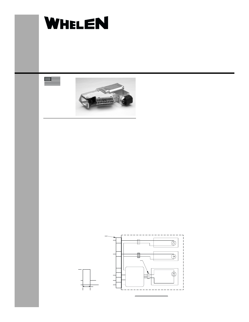
Position/Anti-Collision Light Assembly
Model(s):
7100001, 7100002, 7100003, 7100004
01-0771000-01, 01-0771000-02
01-0771000-03, 01-0771000-04
Aviation
©2005 Whelen Engineering Company Inc.
Form No.14009A (091605)
®
ENGINEERING COMPANY INC.
Route 145, Winthrop Road,
Chester, Connecticut 06412
Phone: (860) 526-9504
Fax: (860) 526-2009
Internet: www.whelen.com
Sales/Service e-mail: [email protected]
MADE IN THE U.S.A.
TSO-C96a
CLASS III
APPROVED
OPERATING INSTRUCTIONS:
LED POSITION LIGHT
28VDC (NOM.)
0.3 AMPS
LED ANTI-COLLISION LIGHT
28VDC (NOM.)
4.0 AMPS @ .25 SEC.
RECOGNITION LIGHT
28VDC (NOM.)
1.25 AMPS
The conditions and tests required for TSO approval of this
article are minimum performance standards. It is the
responsibility of those installing this article either on or
within a specific type or class of aircraft to determine that
the aircraft installation conditions are within the TSO
standards. TSO articles must have separate approval for
installation in aircraft. The article may be installed only if
performed under 14 CFR part 43 or the applicable
airworthiness requirements.
CONTINUED AIRWORTHINESS: The 71000 series Position/
Anti-collision assembly utilizes a Model 71015-series Position
Light designed with 6 LED’s. If any one LED fails, the unit must
be repaired or replaced. The Anti-collision System is designed
with four banks of 5 LED’s. Should any one of the four banks
fail, the unit will automatically shut down and repair or
replacement will be necessary. If any one or two single LED’s
fail, the unit will still meet light output requirements. If three or
more LED’s fail, the unit must be repaired or replaced.
EQUIPMENT LIMITATIONS: The Class
i
III anti-collision system
must produce a minimum of 100 effective candelas in aviation
red or white, 360° around the vertical axis, 30° above and below
the horizontal plane. Model 71000-series Anti-collision Light
Systems will provide 120° of coverage at each wingtip, equal to
240° total coverage. An approved forward position lighting
system consists of two lights. Model 71000 has one light located
on each wingtip.
INSTALLATION PROCEDURES: The following information is
to assist in the installation of a Whelen LED Position/Anti-
Collision Light Assembly.
1.
Choose the appropriate 71000( ) Position/Anti-collision
light assembly which is most applicable to your aircraft.
2.
The installation procedure described in the following text
will be confined to a single light installation, but is identical
for multiple light installations.
3.
Remove old light, locate and save the existing +28VDC
lead and (-) ground lead. Clean and prep lead ends as
required.
4.
Use existing mounting holes and hardware.
5.
Connect the +28 VDC and (-) ground leads equipped with
an appropriate sized breaker to the LED Light. Both leads
must be connected by an approved FAA connection.
6.
Install light assembly and insure that the wire leads are
clear of any obstructions and ty-wrap as required. Use lock
washers and/or thread lock on all threaded fasteners.
7.
Check all avionics systems for interference from the
installation.
8.
A flight check should be performed by a properly certified
pilot.
9.
Update aircraft records, complete Form 337 and obtain
FAA field approval for installation.
3
5
4
INTERNAL SCHEMATIC
2
1
205841-1 CONNECTOR
(REF)
+(28) VDC
+(28) VDC
28 VDC
15.0 MAX
35mS MIN.
TYP SYNC SIGNAL OUTPUT
4.0 MIN
0 V
GROUND
GROUND
FLASHER
CIRCUIT
LED POS. LIGHT
RECOG. LIGHT
QUICK
DISCONNECT
TYP 3 PLCS
ANTI-COLL.
LED MODULE
SYNC WIRE
(see page 2 for part numbers
and corresponding diagram)
TSO-C30c
TYPE I, II
APPROVED