Whelen 7112000 User Manual
Aviation, Engineering company inc, Page 1
Page 1
PIONEERS IN SAFETY SIGNALS
ENGINEERING COMPANY, INC.
R
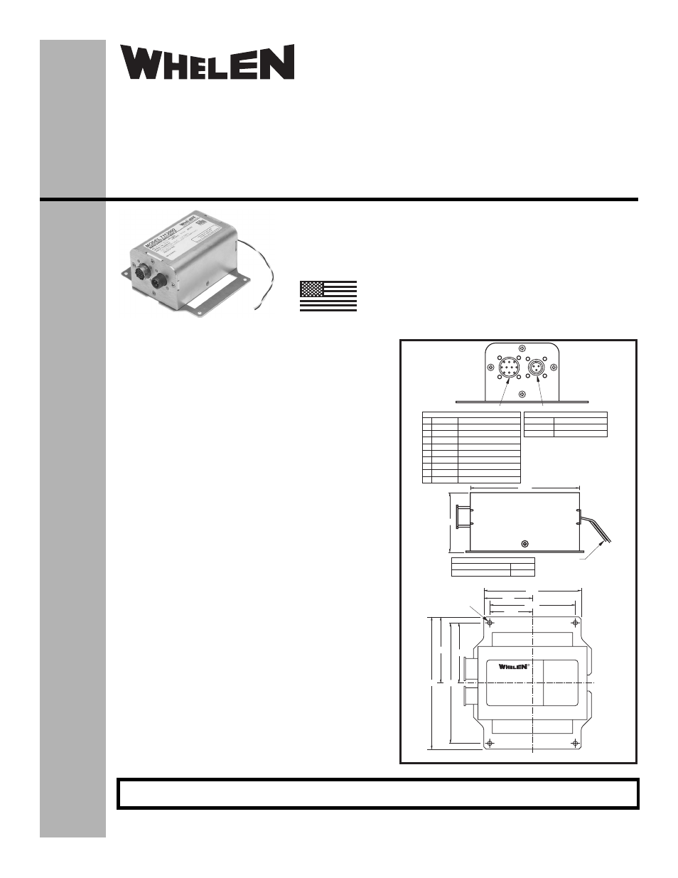
4.13
2.06
5.60
2.80 2.55
5.10
CL
CL
4 x Ø0.188
Mounting Holes
1.812
3.625
A
B
C
D
C
J
E
G
K
F
B A H
A LED1
MS3470L12-10S
B +28V
Anti Collision Light
Anti Collision Light
C LED2
Anti Collision Light
D LED3
Anti Collision Light
E Anode
Rear Position Light
F LED4
Anti Collision Light
J LED5
Anti Collision Light
K LED6
Anti Collision Light
G Anode
Forward Position Light
H Common Position Lights
A
+28V
MS 3102E10SL-3P
B
Ground
C
SYNC
20 GA WHITE WIRE
+28V
WIRE 7.00 ±1.00 LG
20 GA BLACK WIRE Ground
4.63
2.53
Position Lights
Input Wires
Anti-Collision Input Connector
Output Connector
®
ENGINEERING COMPANY INC.
Route 145, Winthrop Road,
Chester, Connecticut 06412
Phone: (860) 526-9504
Fax: (860) 526-2009
Internet: www.whelen.com
Sales/Service e-mail: [email protected]
Aviation
Installation Guide:
Aviation model 7112000
P/N 01-0771120-00
Flasher/Current Source Ass’y
©2007 Whelen Engineering Company Inc.
Form No.14137 (083007)
For warranty information regarding this product, visit www.whelen.com/warranty
SPECIFICATIONS:
Nominal Operational Voltage:............................................ 28 VDC
Current Source Input Current:
LED Forward Position Light ........................................... 0.25 AMPS
LED Tail Position Light.................................................... 0.25 AMPS
LED Anti-Collision Light ([email protected] Sec.)..................... 4.5 AMPS
LED Anti-Collision Light (Avg.) ...................................... 0.85 AMPS
Flashrate.............................................................................. 45 ±5 Per. Min.
Total Weight ........................................................................ 0.95 lbs.
EQUIPMENT LIMITATIONS:
An approved Anti-Collision / Position Light System consists of at
least 2 flasher/current source units, each connected to a LED
anti-collision and position light lighthead model 90325( ), one Red
and one Green.
CONTINUED AIRWORTHINESS:
The forward position light is designed with 6 LED’s. The rear
position light is designed with 3 LED’s. The Anti-Collision light is
designed with 36 LED’s. If any bank of LEDs fail, the lighthead
module should be checked. If the module checks good, replace
the flasher.
Note: The anti-collision light will automatically shut-off after 9-10
flashes if a failure is detected.
INSTALLATION PROCEDURES:
1.
Consider areas or locations designated by the aircraft
manufacturer. Check that breakers are properly rated.
2.
Attach the flasher using the (4) 0.188 dia. mounting holes.
3.
Connect the anti-collision inputs and the position light inputs
according to the chart shown. Connect the cable from
90325( ) to the flasher position light. Connections to be in
accordance with FAA approved methods.
4.
Check all avionic systems for interference from the
installation
5.
A flight check should be performed by a certified pilot
6.
Update aircraft records, complete form 337 and obtain FAA
field approval for installation, as necessary
MADE IN THE U.S.A.
The conditions and tests required for TSO approval of this
article are minimum performance standards. It is the
responsibility of those installing this article either on or
within a specific type or class of aircraft to determine that
the aircraft installation conditions are within the TSO
standards. TSO articles must have separate approval for
installation in aircraft. The article may be installed only if
performed under 14 CFR part 43 or the applicable
airworthiness requirements.
TSO-C30c
TYPES I, II & III /
TSO-C96a
CLASS II
APPROVED