Whelen 9035801 User Manual
Aviation, Engineering company inc
Page 1
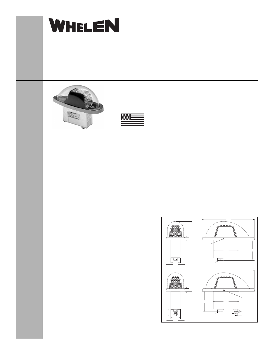
3.67
Drain
Drain
3.67
2.87
2.87
7.48
7.48
2.64
2.64
1.37
2.75
.40
.40
1.37
2.75
1.00
NAS1149CO463R
MS35650-3254 (2)
MS51958-83
MS35338-139
MIL-C-38999 SERIES II
CONNECTOR
MIL-C-38999 SERIES II
CONNECTOR
Models:
9035801
9035802
Models:
9035083
9035804
®
ENGINEERING COMPANY INC.
51 Winthrop Road
Chester, Connecticut 06412-0684
Phone: (860) 526-9504
Fax: (860) 526-2009
Internet: www.whelen.com
Sales/Service e-mail: [email protected]
Aviation
Installation Guide:
Model(s) 9035801, 9035802, 9035803, 9035804
P/Ns 01-0790358-01, 01-0790358-02
01-0790358-03, 01-0790358-04
LED Anti-Collision/LED Position Light Ass’y
©2008 Whelen Engineering Company Inc.
Form No.14198B (020510)
SPECIFICATIONS:
Nominal Operational Voltage:........................ 28 VDC
Input Current:
LED Position Light........................................ 0.5 amps
LED Anti-Collision Light ([email protected] sec) .. 4.2 amps
LED Anti-Collision Light (Average)............... 0.8 amps
Flashrate: ........................................................ 45± 5 per min.
Total Weight
9035801, 9035802 ....................................... 1.3 lbs.
9035803, 9035804 ....................................... 1.35 lbs.
EQUIPMENT LIMITATIONS:
An approved lighting system consists of two lights, one
located on each wingtip. The baseplate must be mounted
parallel to the vertical and horizontal centerlines of the
aircraft to project the patterns properly.
Certain types of installation may require additional testing.
CONTINUED AIRWORTHINESS:
The forward position light is designed with 6 LED’s. The
rear position light is designed with 3 LED’s. The Anti-
Collision light is designed with 36 LED’s. If any one LED
fails, the unit must be repaired or replaced. Inspect the lens.
Replace if there is excessive scratching, pitting,
discoloration or cracking.
Note: The anti-collision light will automatically shut-off after
9-10 flashes if a failure is detected.
INSTALLATION PROCEDURES:
The following information is to assist you in installing a
Whelen Anti-Collision / Position light system.
1.
Choose the appropriate Model 90358( ) replacement
light assembly.
2.
The installation procedure described in the following
text will be confined to a single light installation, but is
identical for multiple light installations.
3.
Connect the anti-collision inputs and the position light
inputs according to the chart shown. Connections to be
in accordance with FAA approved methods.
NOTE: Models 9035803 and 9035804 have an
additional grounding stud.
4.
Using #8 flathead screws, install light assembly and
insure that all leads are clear of any obstructions and
ty-rap as required. Secure light assembly, using
vibration resistant threaded fasteners.
5.
Reinstall the lens.
6.
Check all avionics systems for interference from this
installation.
7.
A flight check should be performed by a properly
certified pilot.
8.
When necessary, waterproof the light base to aircraft.
Apply single part silicone (RTV) or equivalent around
any open area where water could get in. Do not block
the drain hole.
9.
Update aircraft records, complete Form 337 and obtain
FAA field approval for installation, as necessary.
MADE IN THE U.S.A.
The conditions and tests required for TSO approval of this
article are minimum performance standards. It is the
responsibility of those installing this article either on or
within a specific type or class of aircraft to determine that
the aircraft installation conditions are within the TSO
standards. TSO articles must have separate approval for
installation in aircraft. The article may be installed only if
performed under 14 CFR part 43 or the applicable
airworthiness requirements.
TSO-C30c
TYPES I , II & III;
APPROVED
TSO-C96a
CLASS II;
APPROVED