Whelen 7117203 User Manual
Aviation
Page 1
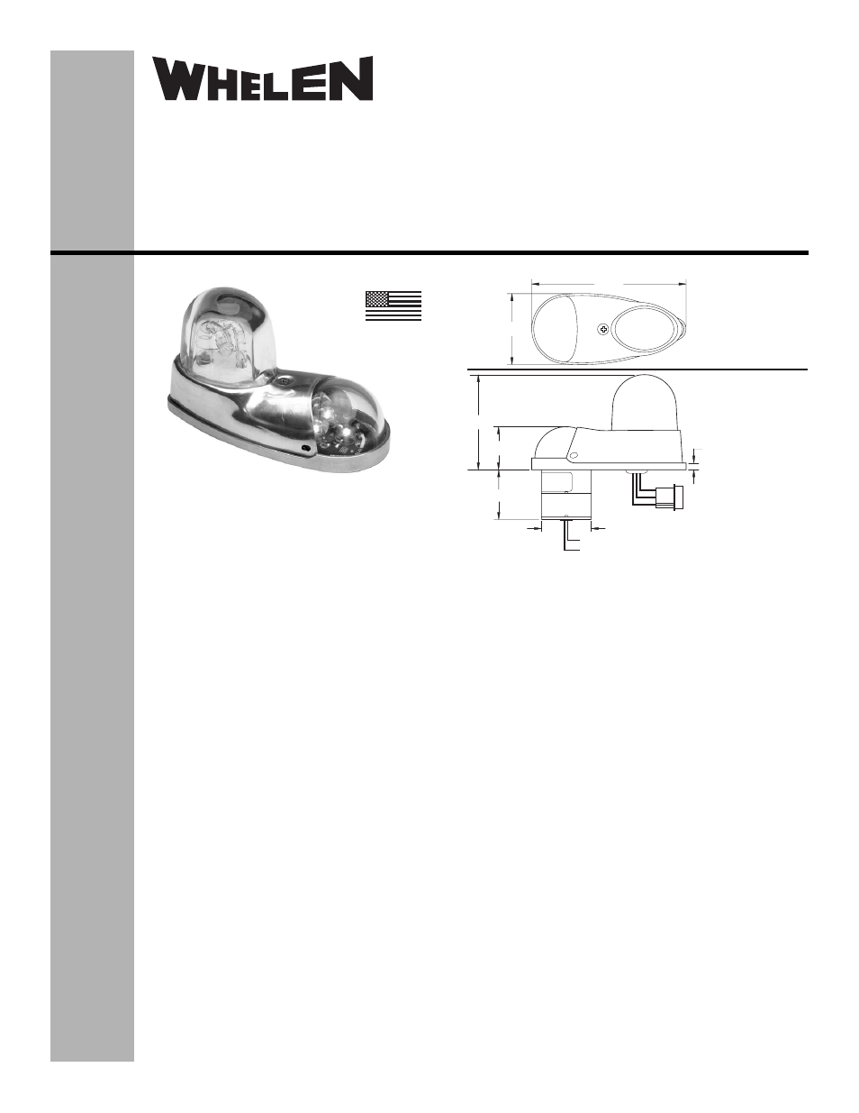
WHITE (+28VDC)
BLACK (-) GROUND
Length - 6.00" ±1.00"
POS 3 - WHITE (TRIGGER)
POS 2 - BLACK (CATHODE)
POS 1 - RED (ANODE)
Length - 6.00" ±1.00"
J1
.17
2.35
1.08
1.15 MIN
Ø1.25
3.88
1.78
7117203
7117204
7117203
7117204
®
ENGINEERING COMPANY INC.
51 Winthrop Road
Chester, Connecticut 06412-0684
Phone: (860) 526-9504
Fax: (860) 526-2009
Internet: www.whelen.com
Sales/Service e-mail: [email protected]
Aviation
©2008 Whelen Engineering Company Inc.
Form No.14203 (061808)
POSITION LIGHT:
Operational Voltage: . . . . . . . 28 VDC (nominal)
Input Current: . . . . . . . . . . . . . 0.25 Amps
EQUIPMENT LIMITATIONS: A lighting system
consists of two lights, one located on each wingtip.
The baseplate must be mounted parallel to the
vertical and horizontal centerlines of the aircraft to
project the patterns properly. The strobe tube
assembly must be connected to a strobe power
supply, such as Whelen model 70888, 70879 or
other approved models.
CONTINUED AIRWORTHINESS: The 71172 series
LED wingtip position light assembly is designed with
3 LED’s. If any one LED fails, the unit must be
repaired or replaced. Inspect the lens. Replace if
there is excessive scratching, discoloration or
cracking.
INSTALLATION PROCEDURES: The following
information is to assist in the installation of a Whelen
71172 LED Forward Position Light/Strobe System.
1.
Choose the appropriate 71172( ) series
replacement light assembly.
2.
The installation procedure described in the
following text will be confined to a single light
installation, but is identical for multiple light
installations.
3.
Remove the old light, locate and save the
existing +VDC lead and (-) ground lead. Clean
and prep ends as required.
4.
Make sure the existing system is equipped with an
appropriate sized breaker. Connect the existing +28
VDC lead to the POSITIVE wire on the input cable
assembly (supplied with the light assembly). Connect the
existing ground lead to the GROUND wire on the input
cable assembly or use the supplied connector as shown
in the illustrations. Both leads must be connected by an
approved FAA connection. Insure that the wire leads are
clear of any obstructions and ty-wrap as required.
Connect the strobe, J1, to the strobe power supply as
shown in the figure.
5.
Remove the shroud from the light assembly.
6.
Position the base of the new light assembly onto the
mounting surface. Insert three (3) #6-32 pan head
screws into the mounting hole and tighten firmly.
7.
Reinstall the lens so that the two notches are positioned
under the shroud, with each notch equidistant to the
centerline.
8.
Check all avionics systems for interference from the
installation.
9.
A flight check should be performed by a properly certified
pilot.
10. Update aircraft records, complete Form 337 and obtain
FAA field approval for installation, as required.
MADE IN THE U.S.A.
Installation Guide: 71172( )-series
Models 7117203, 7117204
P/N: 01-0771172-03, -04
LED Forward Position Light/
Red Strobe Assembly