Whelen 7117051 User Manual
Aviation, Engineering company inc
Page 1
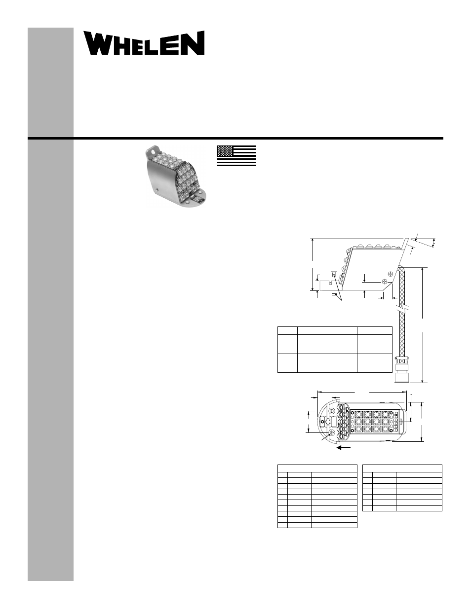
-51,-52
-53,-54
Model
Model 71170( )
MIL 22759/43 20 AWG
wires, Abrasion-resistant
Outer Jacket, RF Braid
MIL 22759/43 20 AWG
wires, Abrasion-resistant
Outer Jacket, RF Braid
24" ±1"
36" ±1"
Cable Details
Cable Length
A
B
C
D
E
F
G
H
J
K
LED1
V+
LED2
LED3
V+
LED4
ANODE
CATHODE
N/C
N/C
Anti-Collision Light
Anti-Collision Light
Anti-Collision Light
Anti-Collision Light
Anti-Collision Light
Anti-Collision Light
Forward Position Light
Forward Position Light
7117051, 7117052 - D38999/26FC98PN
A
B
C
D
E
F
G
LED1
V+
LED2
LED3
LED4
ANODE
CATHODE
Anti-Collision Light
Anti-Collision Light
Anti-Collision Light
Anti-Collision Light
Anti-Collision Light
Forward Position Light
Forward Position Light
7117053, 7117054 - MS27473T10F99P
.970
Mounting Holes
3 x Ø.156
Counter-Sink
.279 x 82°
Ø
Line Of Flight
.638
3.97
.880
1.77
.43"
NOTE: Shroud hardware
must be removed and
discarded prior to mounting.
.38"
.44"
20°
.290"
2.33"
Cable Length
(see table)
Forward
®
ENGINEERING COMPANY INC.
51 Winthrop Road
Chester, Connecticut 06412-0684
Phone: (860) 526-9504
Fax: (860) 526-2009
Internet: www.whelen.com
Sales/Service e-mail: [email protected]
Aviation
Installation Guide:
Model 71170( ) Series
Models: 7117051, 7117052,
7117053, 7117054
P/N: 01-0771170-51, -52, -53, -54
LED Wingtip Anti-Collision /
Position Light Assembly
©2009 Whelen Engineering Company Inc.
Form No.14328C (031411)
The conditions and tests required for TSO approval of this
article are minimum performance standards. It is the
responsibility of those installing this article either on or
within a specific type or class of aircraft to determine that
the aircraft installation conditions are within the TSO
standards. TSO articles must have separate approval for
installation in aircraft. The article may be installed only if
performed under 14 CFR part 43 or the applicable
airworthiness requirements.
SPECIFICATIONS:
Nominal Operational Voltage: ...............................28 VDC
Input Current (with 7123403 Flasher):
LED Position Light:...................................................0.25 Amps
LED Anti-Collision Light (Average):..........................0.53 Amps
LED Anti-Collision Light ([email protected] sec.): ............2.8 Amps
Flashrate ..................................................................45± 5 per min.
EQUIPMENT LIMITATIONS:
An approved forward position and anti-collision system consists of at
least two lightheads, one mounted on each wingtip mounted behind a
clear lens, and each connected to a model 71234( ) Flasher.
Certain types of installations may require additional testing.
CONTINUED AIRWORTHINESS:
The wingtip anti-collision light is designed with 24 LEDs. The position
light is designed with 6 LEDs. If any one fails, the unit must be
repaired or replaced. NOTE: To reduce eye strain, use an optical filter
(such as dark glasses or a blue covering dome) during LED
inspection.
Note: The anti-collision lights will automatically shut-off after 9-10
flashes if a failure is detected.
SHROUD REMOVAL PROCEDURE:
If justified by the Aircraft installation and additional FAA testing of
compliance to TSO-C30c and TSO-C96a the shroud may be
removed.
1.
Remove and discard the two, #6 screws that are used to secure
the shroud. Carefully remove the shroud. CAUTION: Do not
touch the LED lens.
INSTALLATION PROCEDURE:
The following information is to assist you in installing a Whelen anti-
collision light system.
1.
The installation procedure described in the following text will be
confined to a single light installation, but is identical for multiple
light installations.
2.
Connect the inputs according to the chart shown. Connections
to be in accordance with FAA approved methods.
3.
Using appropriate, approved hardware, install light assembly
and insure that all leads are clear of any obstructions and ty-rap
as required. Secure light assembly, using vibration resistant
threaded fasteners.
4.
Check all avionics systems for interference from this installation.
5.
A flight check should be performed by a properly certified pilot.
6.
Update aircraft records, complete Form 337 and obtain FAA
field approval for installation, as necessary.
MADE IN THE U.S.A.
TSO-C30c
TYPE I & II;
APPROVED
TSO-C96a
CLASS II;
APPROVED
(Shroud not shown)