Whelen 9048200 User Manual
Aviation
Page 1
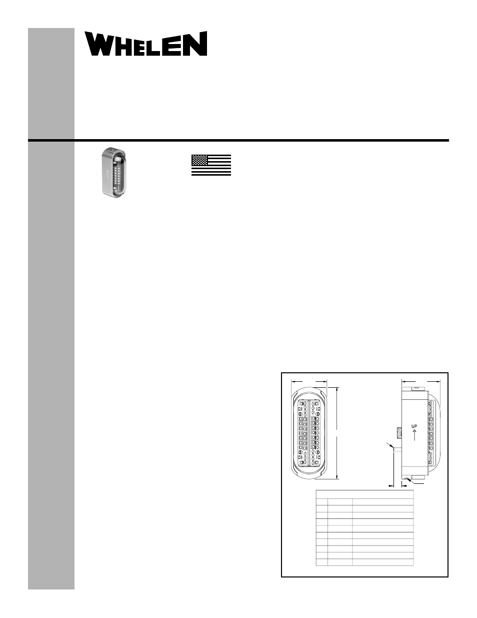
1
2
3
4
5
6
7
8
9
10
LED1
V+
LED2
LED3
V+
LED4
Anode
Cathode
Anode
Cathode
(Mating Connector 801-008-16M7-10SA)
Anti-Collision Light
Anti-Collision Light
Anti-Collision Light
Anti-Collision Light
Anti-Collision Light
Anti-Collision Light
Rear Position Light
Rear Position Light
Ground Recognition Light
Ground Recognition Light
Glenair 801-010-02M7-10PA
1.51
Drain
Hole
6-32
Grounding
Stud
.41
1.40
3.60
®
ENGINEERING COMPANY INC.
51 Winthrop Road
Chester, Connecticut 06412-0684
Phone: (860) 526-9504
Fax: (860) 526-2009
Internet: www.whelen.com
Sales/Service e-mail: [email protected]
Aviation
Installation Guide:
Aviation model 9048200
P/N 01-0790482-00
LED Tail Position /
Ground Recognition /
Anti-Collision Light Assembly
©2010 Whelen Engineering Company Inc.
Form No.14329A (091411)
SPECIFICATIONS:
Nominal Operational Voltage: ...............................28 VDC
Input Current (with 7123403 Flasher):
LED Tail Position Light: ............................................0.25 Amps
LED Anti-Collision Light (Average):..........................0.53 Amps
LED Anti-Collision Light ([email protected] sec.):.............2.8 Amps
LED Ground Recognition Light (Average):...............0.13 Amps
LED Ground Recognition Light ([email protected] sec.):..0.7 Amps
Flashrate ..................................................................45± 5 per min.
EQUIPMENT LIMITATIONS:
An approved lighting system consists of three lights, one
located on the tail and one located on each wingtip. The
baseplate must be mounted parallel to the vertical and
horizontal centerlines of the aircraft to project the patterns
properly. The light assembly must be connected to flasher
assembly, model 7123403.
The ground recognition light is a non-TSO function.
Certain types of installations may require additional testing.
CONTINUED AIRWORTHINESS:
The tail position light is designed with 4 LEDs. The anti-collision
light is designed with 28 LEDs. The ground recognition light is
designed with 4 LEDs. If any one LED fails, the unit must be
repaired or replaced. Note: To reduce eye strain, use an optical
filter (such as dark glasses or blue covering dome) during LED
inspection.
Inspect the lens. Replace if there is excessive scratching,
pitting, discoloration or cracking.
Note: The anti-collision light will automatically shut-off after 9-
10 flashes if a failure is detected.
INSTALLATION PROCEDURES:
1.
Using the mounting detail information on page 2, prepare
the aircraft for means to secure the LED light assembly.
Remove any existing mounting adapters.
2.
Connect the light inputs according to the chart shown.
Connections to be in accordance with FAA approved
methods.
3.
Remove 4 (2-56) screws to remove retainers. Carefully
remove lens. Remove 3 (4-40) screws to remove mounting
plate. CAUTION! Do not touch the LED lens surface with
either fingers or sharp objects. This could soil and/or
damage the lens and affect the optical performance of the
LEDs.
4.
Install the mounting baseplate by securing to the aircraft
using appropriate, approved hardware (refer to page 2).
Attach the light assembly using three screws. Insure
that all leads are clear of any obstrtuctions, and secure
as required.
Insure that the gasket drain holes are
oriented as shown on Page 2.
5.
Reinstall lens, confirm proper gasket fit and secure
using retainers and screws.
6.
When necessary, waterproof the lightbase to aircraft.
Apply single-part Silicone (RTV) or equivalent around
any open area where water could get in. Do not cover
the drain holes.
7.
Check all avionics systems for interference from this
installation.
8.
A flight check should be performed by a properly
certified pilot.
9.
Update aircraft records, complete Form 337 and obtain
FAA field approval for installation, as required.
MADE IN THE U.S.A.
The conditions and tests required for TSO approval of this article are
minimum performance standards. It is the responsibility of those
installing this article either on or within a specific type or class of
aircraft to determine that the aircraft installation conditions are within
the TSO standards. TSO articles must have separate approval for
installation in aircraft. The article may be installed only if performed
under 14 CFR part 43 or the applicable airworthiness requirements.
TSO-C30c
TYPE III;
APPROVED
TSO-C96a
CLASS II;
APPROVED