Whelen 9045600 User Manual
Aviation, Engineering company inc
Page 1
®
ENGINEERING COMPANY INC.
Aviation
CHESTER, CONNECTICUT 06412-0684
ENGINEERING COMPANY, INC.
BY:
R
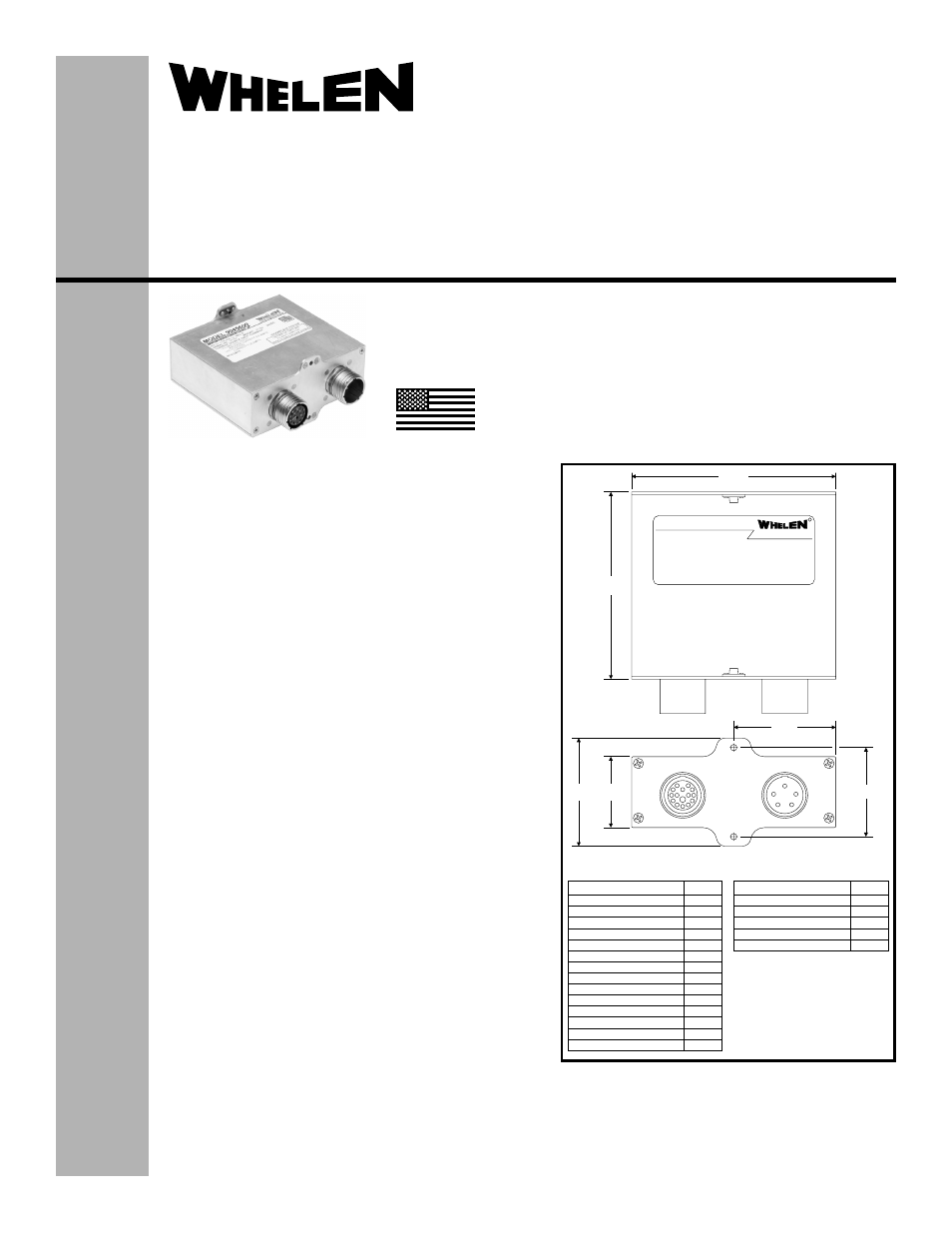
MODEL 9045600
4.50
4.12
J2
J1
J2
J1
2.38 1.56
1.96±.01
2.25
M
K
L
A
R
J
H
G
N
C
D
F
Anode A
Cathode A1
Cathode A2
Cathode A3
Anode B
Cathode B1
Cathode B2
Cathode B3
Anode
Cathode 1
Cathode 2
Anti-Collision
Anti-Collision
Anti-Collision
Anti-Collision
Anti-Collision
Anti-Collision
Anti-Collision
Anti-Collision
Position
Position
Position
Fault Indicator
J2-D38999/20FD15SN
Contact
A
B
C
D
E
+28V
GND
+28V
Anti-Collision
Ground
SYNC
Position
No Connector
J1-D38999/20FD5PN
Contact
Installation Guide:
Aviation model 9045600
P/N 01-0790456-00
Flasher/Current Source
©2010 Whelen Engineering Company Inc.
Form No.14423 (100110)
SPECIFICATIONS:
Nominal Operational Voltage:............................... 28 VDC
(Operation from 24-32 VDC)
Input Current (with 90453( ) Lighthead):
LED Position Light ............................................. 0.25 Amps
LED Anti-Collision Light (Avg.) ......................... 0.6 Amps
LED Anti-Collision Light ([email protected] Sec.) ...... 3.0 Amps
Flashrate................................................................. 45 ±5 Per. Min.
EQUIPMENT LIMITATIONS:
An approved forward lighting system consists of at least two flasher/
current sources, each connected to a LED position/anti-collision
lighthead such as model 90453( ).
The maximum length of the interface cable between the light assembly
and the flasher/current source is 20 feet using 20 AWG wire.
Certain types of installations may require additional testing.
CONTINUED AIRWORTHINESS:
If any one bank of LEDs fail, the lighthead module should be
checked. If the module checks good, replace the flasher.
Note: The system has an internal diagnostic circuit to detect failures.
After 20-25 seconds if a failure is detected the amber fault light will
illuminate.
INSTALLATION PROCEDURES:
The following information is to assist you in installing a Whelen light
system. the installation procedure described in the following text will
be confined to a single light installation, but is identical for multiple
light installations.
1.
Consider areas or locations designated by the aircraft
manufacturer. Check that breakers are properly rated.
2.
Using appropriate hardware. install the flasher assembly using
the 4 self-locking anchor nuts.
3.
Connect the inputs according to the chart shown. Connections
to be in accordance with FAA approved methods. Insure that all
leads are clear of any obstructions and ty-wrap as required.
4.
Check all avionic systems for interference from the installation
5.
A flight check should be performed by a certified pilot
6.
Update aircraft records, complete form 337 and obtain FAA
field approval for installation, as necessary
MADE IN THE U.S.A.
The conditions and tests required for TSO approval of this
article are minimum performance standards. It is the
responsibility of those installing this article either on or
within a specific type or class of aircraft to determine that
the aircraft installation conditions are within the TSO
standards. TSO articles must have separate approval for
installation in aircraft. The article may be installed only if
performed under 14 CFR part 43 or the applicable
airworthiness requirements.
TSO-C30c
TYPES I & II /
TSO-C96a
CLASS II
APPROVED
51 Winthrop Road
Chester, Connecticut 06412-0684
Phone: (860) 526-9504
Fax: (860) 526-2009
Internet: www.whelen.com
Sales/Service e-mail: [email protected]