Whelen 7155407 User Manual
Aviation, Engineering company inc
Page 1
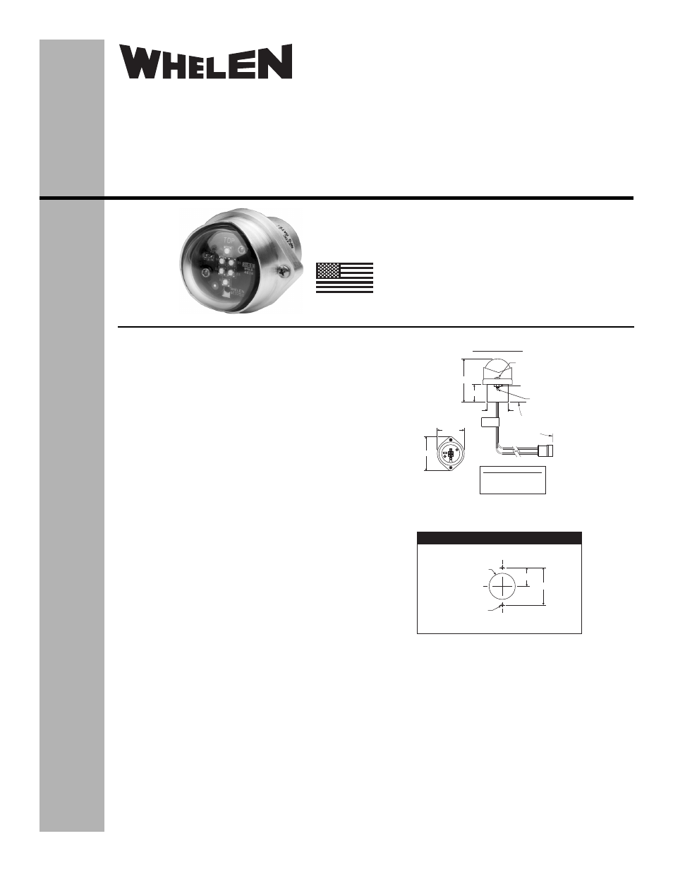
4-40 X 5/8"
MS51957-18 (2X)
VERTICAL
01-0771554-07
Nut (for shipping
purposes only)
Drain Hole
TOP
2.16"
1.71"
1.13"
.96"
2.36"
Model:
7155407
C
L
CL
Mounting Detail
Ø.125
(2 Places)
Ø.123
0.875
1.750
SJS840351 Connector
POS A = 28VDC, WHT
POS B = Ground, BLK
POS C = N/C
20 AWG/MIL 22759/43
Lead Length-
6.0”, +1.0”/-0.5”
The conditions and tests required for TSO approval of this
article are minimum performance standards. It is the
responsibility of those installing this article either on or
within a specific type or class of aircraft to determine that
the aircraft installation conditions are within the TSO
standards. TSO articles must have separate approval for
installation in aircraft. The article may be installed only if
performed under 14 CFR part 43 or the applicable
airworthiness requirements.
Aviation
Installation Guide:
Model 7155407
P/N: 01-0771554-07
LED Tail Position
Light Assembly
©2014 Whelen Engineering Company Inc.
Form No.14758 (011614)
TSO-C30c
TYPE III
APPROVED
MADE IN THE U.S.A.
OPERATING INSTRUCTIONS:
Nominal Operational Voltage:. .28 VDC
(Operation from 22-30 VDC)
Input Current:. . . . . . . . . . . . . . .0.125 Amps
EQUIPMENT LIMITATIONS: An approved tail position light
assembly should be mounted as far aft on the aircraft as
practicable on a thermally conductive surface. The
baseplate must be mounted parallel to the vertical and
horizontal centerlines of the aircraft to project the patterns
properly.
Certain types of installations may require additional testing.
CONTINUED AIRWORTHINESS: The 7155407series LED
tail position light assembly is designed with 6 LEDs. Should
any one LED fail the unit must be repaired or replaced.
Note: To reduce eye strain, use an optical filter such as dark
glasses or a blue covering dome during LED inspection.
Inspect the lens. Replace if there is excessive scratching,
pitting, discoloration or cracking.
INSTALLATION PROCEDURES: The following information
is to assist you in installing a Whelen LED tail position light.
1.
Using the mounting detail information provided,
prepare the aircraft for means to secure the LED light
assembly.
2.
Connect the position light inputs according to the chart
shown. Connect the power lead to an appropriate sized
breaker. Connections to be in accordance with FAA
approved methods.
3.
Remove and discard the two screws and nuts holding
the retainer to the unit. Carefully remove the lens
retainer and lens from the assembly. CAUTION! Do not
touch the LED surface with either fingers or sharp
objects. This could soil or damage the lens and effect
the optical performance of the LEDs.
4.
Install light assembly and insure that all leads are clear
of any obstructions. Note that proper orientation is
achieved with the drain hole down.
5.
Reinstall the lens and confirm proper gasket fit.
6.
Install the lens retainer. Using appropriate hardware secure as
required. Secure light assembly using vibration resistant threaded
fasteners.
7.
When necessary, waterproof the light base to aircraft. Apply
single part silicone (RTV) or equivalent around any open area
where water could get in. Do not cover drain hole.
8.
Check all avionics systems for interference from this installation.
9.
A flight check should be performed by a properly certified pilot.
10. Update aircraft records, complete Form 337 and obtain FAA field
approval for installation, as necessary.
®
ENGINEERING COMPANY INC.
51 Winthrop Road
Chester, Connecticut 06412-0684
Phone: (860) 526-9504
Fax: (860) 526-2009
Internet: www.whelen.com
Sales/Service e-mail: [email protected]