Installation, 1 hardware description, 1 switch front panel – PLANET WGSW-48040HP User Manual
Page 21
User’s Manual of WGSW-48040HP
2. INSTALLATION
This section describes the hardware features and installation of the Managed Switch on the desktop or rack mount. For easier
management and control of the Managed Switch, familiarize yourself with its display indicators, and ports. Front panel
illustrations in this chapter display the unit LED indicators. Before connecting any network device to the Managed Switch, please
read this chapter completely.
2.1 Hardware Description
2.1.1 Switch Front Panel
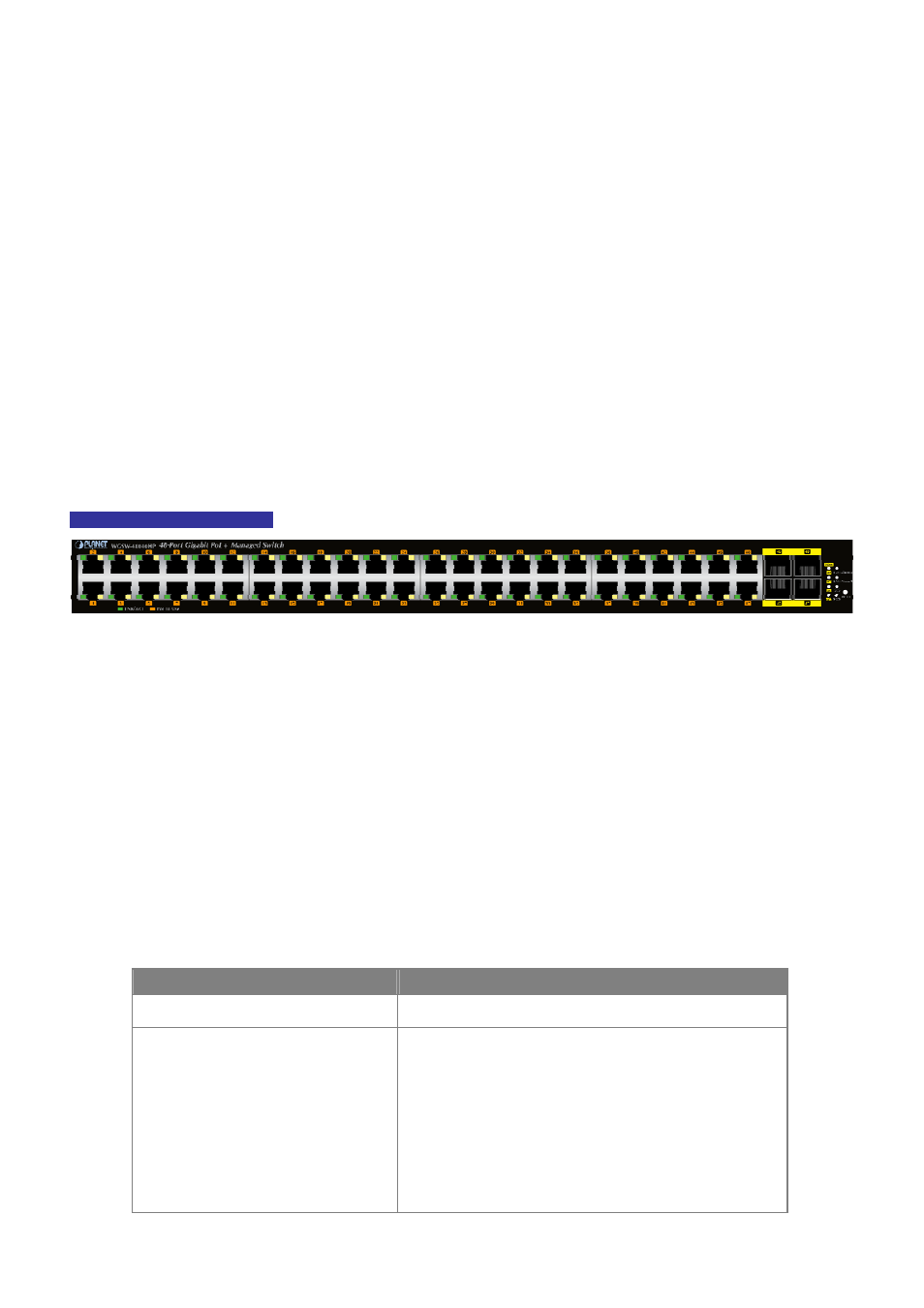
The front panel provides a simple interface monitoring the Managed Switch.
Figure 2-1-1
shows the front panel of the Managed
Switch.
WGSW-48040HP Front Panel
Figure 2-1-1: Front Panels of WGSW-48040HP
■
Gigabit TP interface
10/100/1000Base-T Copper, RJ-45 Twist-Pair: Up to 100 meters.
■
SFP slots
100/1000Base-X mini-GBIC slot, SFP (Small Factor Pluggable) transceiver module: From 550 meters to 2km (multi-mode
fiber), up to above 10/20/30/40/50/70/120 kilometers (single-mode fiber).
■
Reset button
At the right of the front panel, the reset button is designed for rebooting the Managed Switch without turning off and on the
power. The following is the summary table of reset button functions
:
Reset Button Pressed and Released
Function
< 5 sec: System Reboot
Reboot the Managed Switch.
> 5 sec: Factory Default
Reset the Managed Switch to Factory Default configuration.
The Managed Switch will then reboot and load the default
settings as shown below:
。
Default Username:
admin
。
Default Password:
admin
。
Default IP address:
192.168.0.100
。
Subnet mask:
255.255.255.0
。
Default Gateway:
192.168.0.254
21