PLANET CAM-ISD52 User Manual
Page 29
.
.
User’s manual
28
Impedance setup for the speed dome
Each speed dome camera has a termination resistor built in.
In a network of RS-485 chain, the speed domes are classified in two categories:
end unit
(such as the #31) and node (such as #1 through #30).
To set up the resistor correctly, installer must decide if the specific dome camera is
the termination device or not, i.e. if it is at the end of the RS-485 chain.
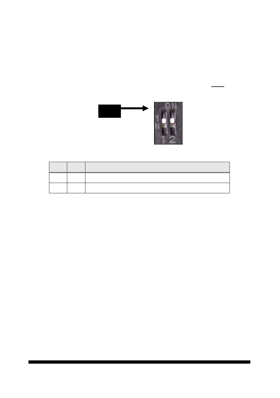
The impedance setup is provided by the bit 1 and bit 2 of DIP switch
DS3
.
Bit 1
Bit 2
Impedance
-- --
Open ( device on node )
On On
Standard 120 ohms ( device at end )
For nodes:
Set both of Bit 1 and Bit 2 to OFF position
For end unit: Set both of Bit 1 and Bit 2 to ON position
Impedance of the control unit
This is generally for two cases: controller with RS-485, and controller with RS-232.
Controller with RS-485:
Most keyboard and video server in market have RS-485, which are equipped with
termination resistor to drive a RS-485 system.
But most PC and notebook sort of devices have RS-232 or USB port but no RS-485.
Therefore, for PC system, a RS-232 or USB to RS-485 converter is required. So
installer must check out if the converter has proper termination resistor.
Problems in practical connection
In some circumstances user adopts a star configuration in practical connection. The
termination resistors must be connected to the two equipment that are farthest
away from each other, such as equipment 1# and 15# in the following picture. As
the star configuration is not in conformity with the requirements of RS-485
DS3