Altera Cyclone V GT FPGA User Manual
Page 15
Chapter 4: Development Board Setup
4–3
Factory Default Switch and Jumper Settings
September 2014
Altera Corporation
Cyclone V GT FPGA Development Kit
User Guide
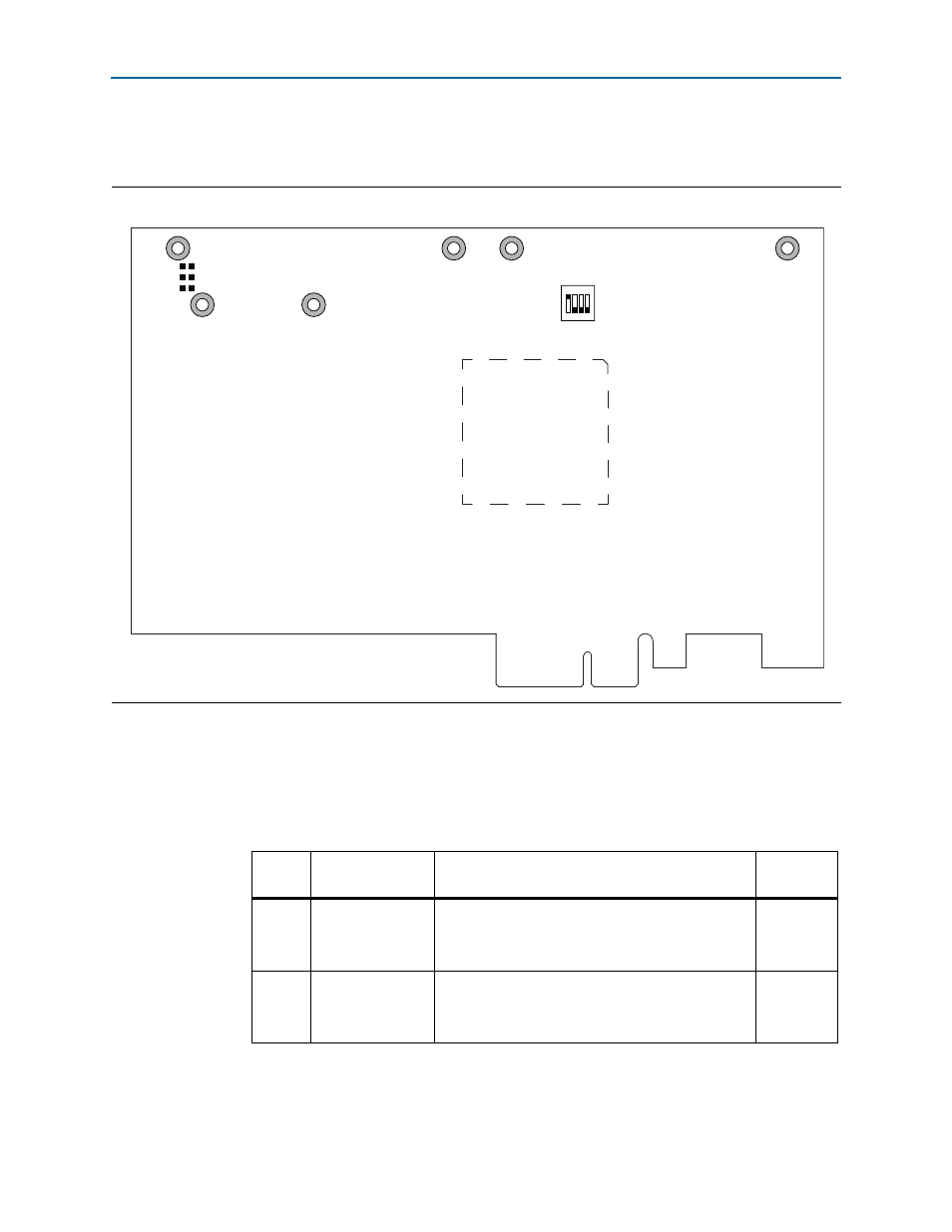
shows the default switch and jumper settings for the bottom side of the
Cyclone V GT FPGA development board.
1
The following tables do not describe user DIP switches.
To restore the switches to the default settings, do the following:
1. Set the DIP switch bank (SW3) to match
and
.
Figure 4–2. Default Switch Settings on the Board Bottom
J17
C5_VCCIO_VAR
(Not installed = 2.5V)
1.2V
5
1
1
0
1.5V
1.8V
SW5
MSEL1 MSEL2 MSEL4 FAN
ON
1 2 3 4
Table 4–1. SW3 DIP Switch Settings (Part 1 of 2)
Switch
Board
Label
Function
Default
Position
1
PCIe_X1
Switch 1 has the following options:
■
ON (logical 0) = x1 presence detect is enabled.
■
OFF (logical 1) = x1 presence detect is disabled.
ON
2
PCIe_X4
Switch 2 has the following options:
■
ON (logical 0) = x4 presence detect is enabled.
■
OFF (logical 1) = x4 presence detect is disabled.
ON