Restoring the max v cpld to the factory settings – Altera Cyclone V GT FPGA User Manual
Page 17
Chapter 4: Development Board Setup
4–5
Restoring the MAX V CPLD to the Factory Settings
September 2014
Altera Corporation
Cyclone V GT FPGA Development Kit
User Guide
f
For more information on the MSEL modes, refe
4. Set the J17 jumper block to match
. The C5_VCCIO_VAR
power rail provides the voltage to bank 7, which connects to the HSMB interface.
By default this rail is 2.5 V. If needed, you can change the voltage level of this
power supply by adding in a jumper wire between the pins of J17 as indicated in
f
For more information about the FPGA board settings, re
.
Restoring the MAX V CPLD to the Factory Settings
This section describes how to restore the original factory contents to the MAX V
CPLD on the FPGA development board. Make sure you have the Nios II EDS
installed, and do the following:
1. Set the board switches to the factory default settings described in
Switch and Jumper Settings” on page 4–2
.
2. Start the Quartus II Programmer.
3. Click Auto Detect.
4. Click Add File for the 5M2210 MAX V device and select <install
dir>\kits\cycloneVGT_5cgtfd9ef35_fpga\factory_recovery\max5.pof.
5. Turn on the Program/Configure option for the added file.
6. Click Start to download the selected configuration file to the MAX V CPLD.
Configuration is complete when the progress bar reaches 100%.
3
MSEL4
Switch 3 has the following options:
■
When ON, a logic 0 is selected.
■
When OFF, a logic 1 is selected.
OFF
4
FAN
Switch 4 has is an optional user switch setting. It
is not currently defined in the MAX 5 system
controller.
OFF
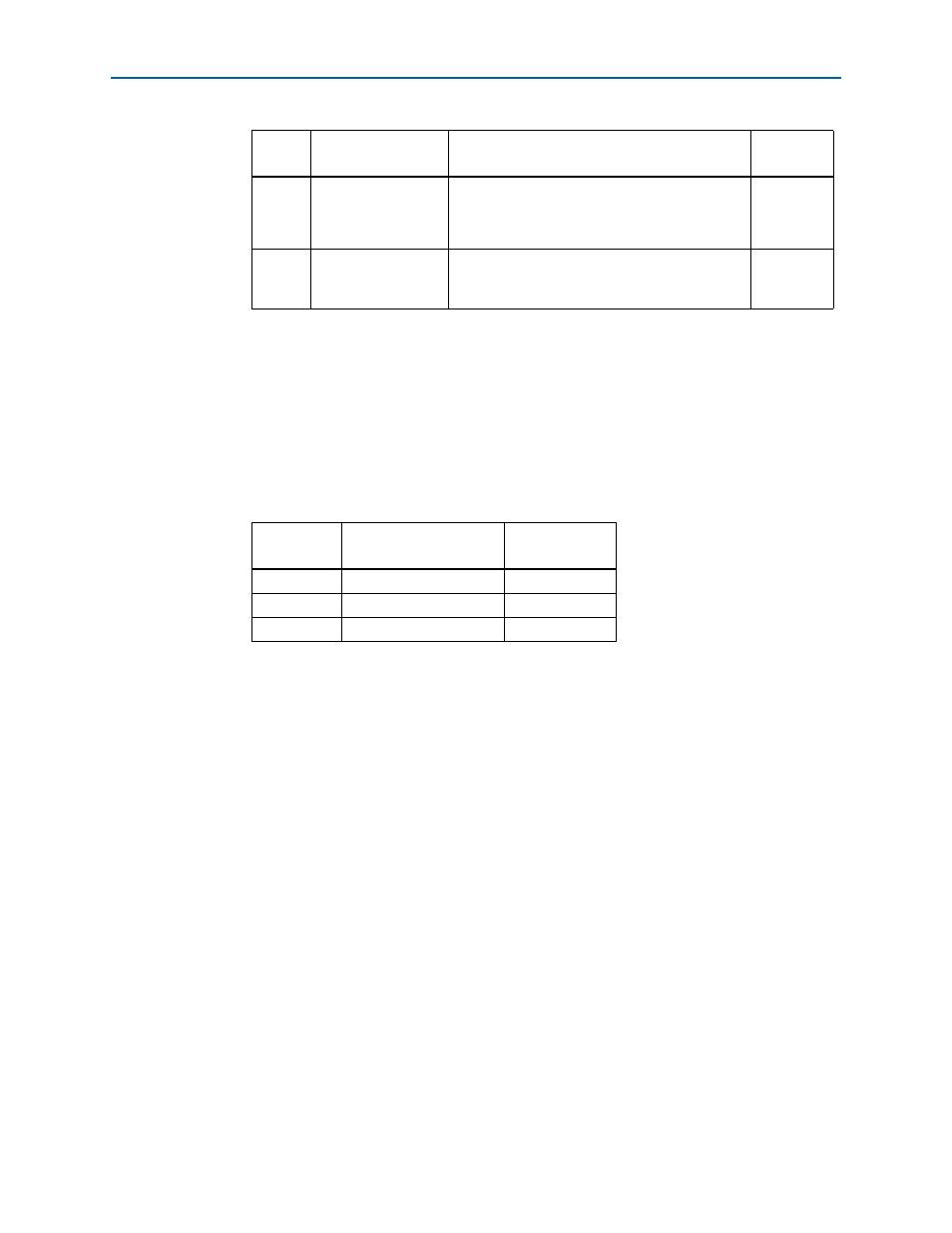
Table 4–4. J17 Jumper Block
Jumper C5_VCCIO_VAR
Default
Position
Pins 1-2
1.8 V
Not installed
Pins 3-4
1.5 V
Not installed
Pins 5-6
1.2 V
Not installed
Note to
:
(1) Adding a single jumper between the pins sets the voltage as
described in the table. Install only one jumper location at a time.
Table 4–3. SW5 DIP Switch Settings (Part 2 of 2)
Switch
Board
Label
Function
Default
Position