Altera SDI HSMC User Manual
Page 15
Chapter 2: Board Components
2–7
Clock Circuitry
© July 2009 Altera Corporation
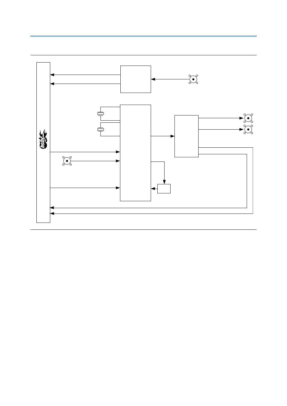
The SDI multi-frequency VCXO femto clock video PLL (ICS810001-21) is utilized for
the SDI reference clocks. The board inputs two crystals to the clock generator, a
27 MHz and 26.973027 MHz. The two frequencies allow low-jitter operation for US
and European SDI standard rates. The HSMC signal SDI_XTAL_SEL determines
which crystal is locked by the internal VCXO.
Clock inputs to the SDI PLL come from the HSMC host or through an SMA input.
Both inputs are end-terminated at 50
Ω to ground. The HSMC signal SDI_CLK_SEL
determines which input is active.
f
For more information on the SDI multi-frequency VCXO femto clock video PLL, refer
to the data sheet provided by IDT.
shows the SDI multi-frequency VCXO femto clock video PLL block
diagram.
Figure 2–3. SDI HSMC Clocking Diagram
Clock
Generator
Video Sync
Separator
Video In
PLL Settings
SDI CLK
HSYNC
VSYNC
LF
EXT CLK IN
EXTCLK_OUT (P)
SDI HSMC CLK
Differential
Buffer
EXTCLK_OUT (N)
SDI CLK (N)
SDI CLK (P)
27.000 MHz
26.973 MHz