Altera SDI HSMC User Manual
Page 21
Chapter 2: Board Components
2–13
Clock Circuitry
© July 2009 Altera Corporation
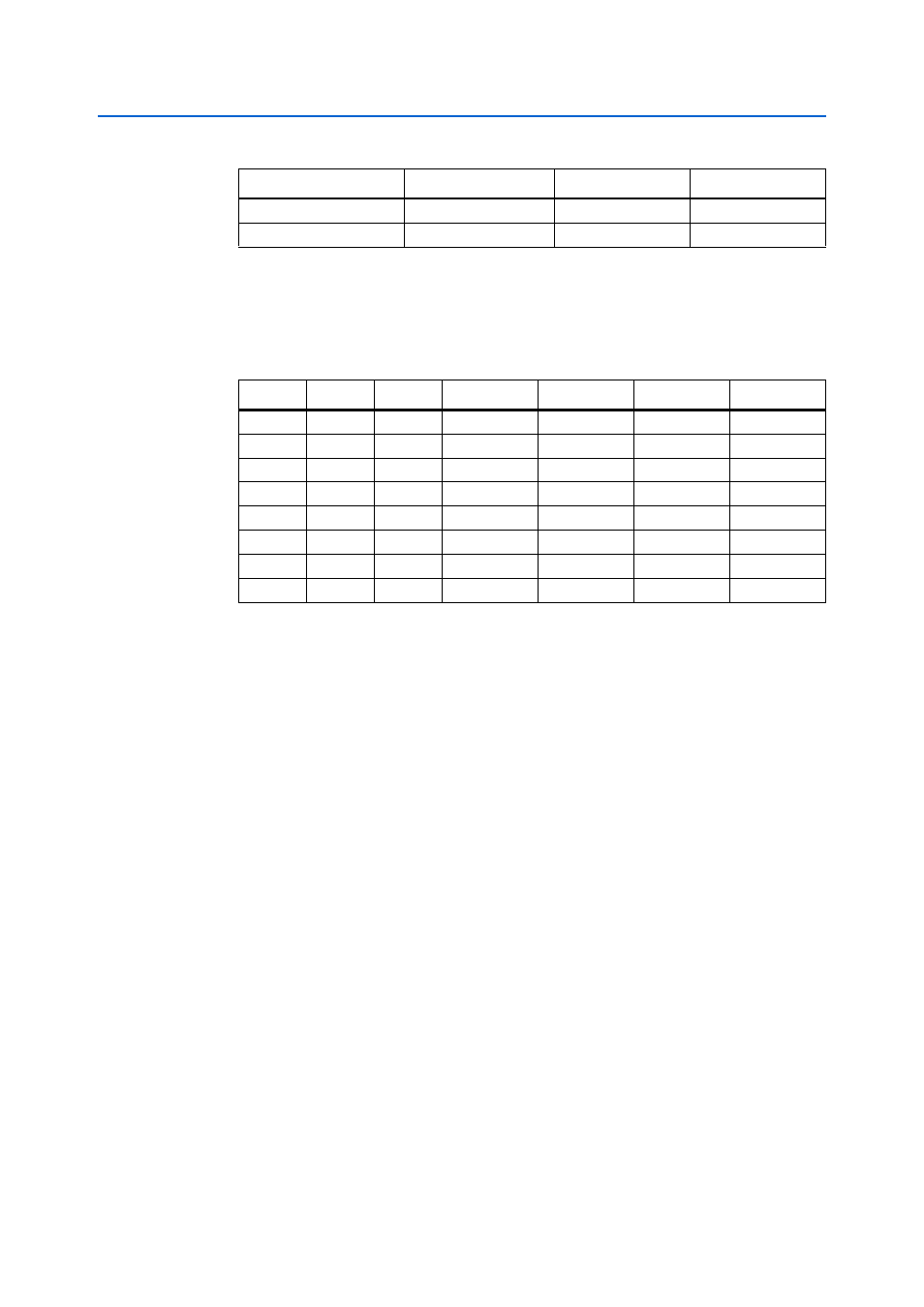
defines the frequency output with respect to the three 1-bit control signals,
S[2:0]
. Outputs from CLK3 and CLK4 are not used in the VCXO PLL. The
frequencies programmed into the VCXO PLL support 4x and 5x over-sampling of the
most popular audio sample rates.
176.4
22.5792
5
112.8960
192
24.5760
5
122.8800
Table 2–10. VCXO PLL Frequency Output
S2
S1
S0
CLK1 (MHz)
CLK2 (MHz)
CLK3
CLK4
0
0
0
98.304
98.304
OFF
OFF
0
0
1
90.3168
90.3168
OFF
OFF
0
1
0
122.88
122.88
OFF
OFF
0
1
1
112.896
112.896
OFF
OFF
1
0
0
98.304
122.88
OFF
OFF
1
0
1
90.3168
112.896
OFF
OFF
1
1
0
98.304
90.3168
OFF
OFF
1
1
1
122.88
112.896
OFF
OFF
Table 2–9. Audio Sample Rate versus Clock Frequency (Part 2 of 2)
Audio Sample Rate (kHz)
Bit Rate Clock (MHz)
Oversampling Rate
VCXO Frequency