Altera SDI HSMC User Manual
Page 24
2–16
Chapter 2: Board Components
Audio/Video Input and Output
© July 2009 Altera Corporation
The SDI TX channel transmit 270 Mbps, 1.485 Gbps and 2.970 Gbps rates using a 75-
Ω
coaxial cable. The SDI signals traverses an impedance matching network provided by
the manufacturer and then goes through a DC blocking capacitor before being sent to
the BNC connector. The output signal is back-terminated to 3.3 V externally with 75-
Ω
resistors. The output DC blocking capacitors consist of 4.7-µF capacitors. The opposite
leg of the SDI cable driver’s differential output pin is terminated in the same way as
the output signal and serves to correctly balance the output currents internal to the
device.
The output of the TX pins on the HSMC host boards should not be installed with DC
blocking capacitors. If DC blocking capacitors are installed, remove the capacitors and
install 0-
Ω resistors of the same foot print size (0402). The input of the SDI cable driver
is differentially terminated with a 100-
Ω resistor and has 4.7-µF DC blocking
capacitors.
There are bi-colored LEDs next to the TX SDI cable driver. The LEDs are connected to
the 3.3 V_SDI power rail through a 75-
Ω resistor and are controlled by signals
SDI_LED_TX_G
and SDI_LED_TX_R. These signals are connected to the HSMC
connector and driven from the host board. The LEDs illuminates when a zero is
driven on the LED control signals. The voltage drop across the LED is approximately
2.1 V. A zero voltage at the HSMC connector on the LED control signals would cause a
drop of 16 mA.
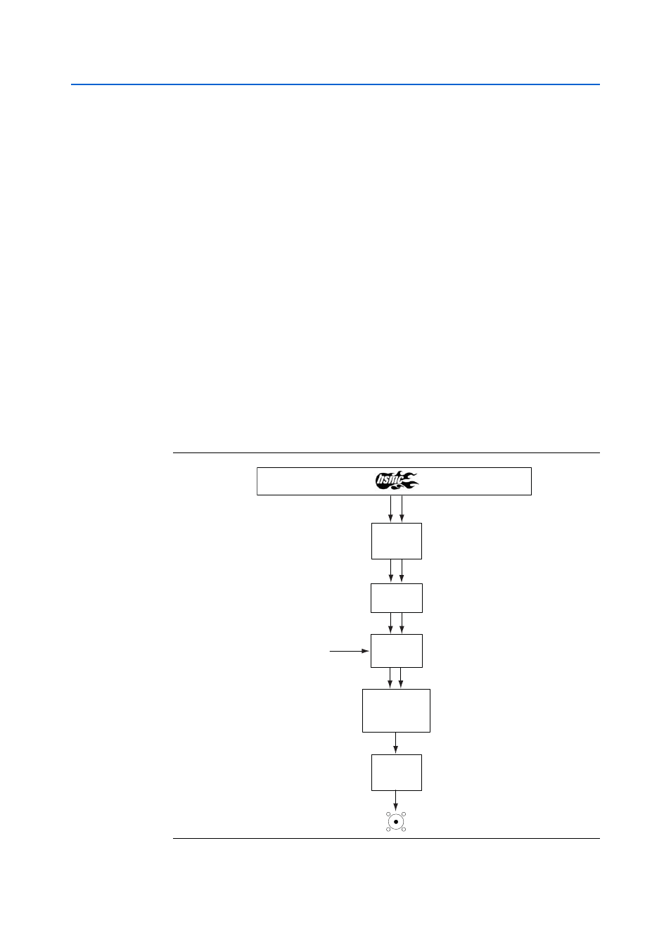
shows the SDI TX channel block diagram.
Figure 2–8. SDI TX Channel Block Diagram
Rate
Sel
SDI Cable
Tri-speed
Driver
LR
Network + Term
SDI TX
DC Block
Diff Term
DC Block