Toggle switch schematic, Figure 2–13 – Altera Cyclone II FPGA Starter Development Board User Manual
Page 36
Advertising
2–18
Reference Manual
Altera Corporation
Cyclone II FPGA Starter Development Board
October 2006
Development Board Components
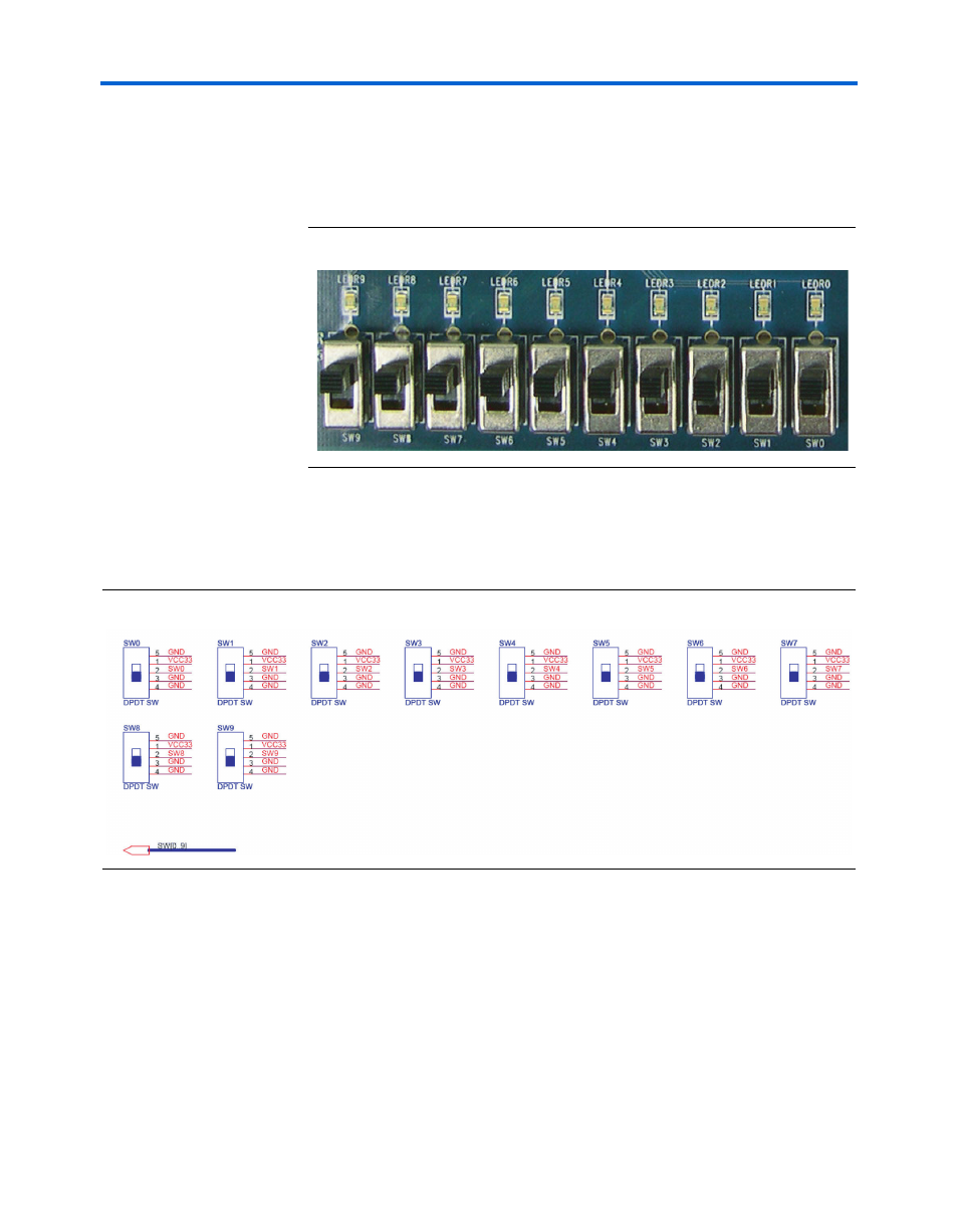
connects directly to a pin on the FPGA. In the DOWN or OFF position
(closest to the edge of the board), a switch provides a LOW logic level (0
volts) to the FPGA. In the UP position a switch provides a HIGH logic
level (3.3 volts).
Figure 2–13. Toggle Switches SW0–SW9 and Red LEDs LEDR0-LEDR9
Toggle Switch Schematic
shows a schematic diagram of the toggle switches.
Figure 2–14. Toggle Switch Schematic Diagram
Advertising