Led pin list, Seven-segment displays – Altera Cyclone II FPGA Starter Development Board User Manual
Page 39
Altera Corporation
Reference Manual
2–21
October 2006
Cyclone II FPGA Starter Development Board
Development Board Components
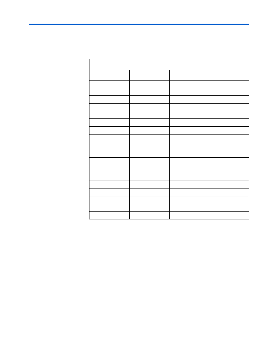
LED Pin List
lists the FPGA pins assigned to the LEDs.
Seven-Segment Displays
The development board provides four adjacent 7-segment displays,
HEX0–HEX3
) for reporting numerical values from the
FPGA. Each segment connects to an FPGA general-purpose I/O pin. A
LOW logic level applied at the pin lights up the segment; a HIGH logic
level turns the segment off.
Table 2–12. LED FPGA Pin Connections
Signal Name
FPGA Pin
Description
LEDR[0]
PIN_R20
LED Red[0]
LEDR[1]
PIN_R19
LED Red[1]
LEDR[2]
PIN_U19
LED Red[2]
LEDR[3]
PIN_Y19
LED Red[3]
LEDR[4]
PIN_T18
LED Red[4]
LEDR[5]
PIN_V19
LED Red[5]
LEDR[6]
PIN_Y18
LED Red[6]
LEDR[7]
PIN_U18
LED Red[7]
LEDR[8]
PIN_R18
LED Red[8]
LEDR[9]
PIN_R17
LED Red[9]
LEDG[0]
PIN_U22
LED Green[0]
LEDG[1]
PIN_U21
LED Green[1]
LEDG[2]
PIN_V22
LED Green[2]
LEDG[3]
PIN_V21
LED Green[3]
LEDG[4]
PIN_W22
LED Green[4]
LEDG[5]
PIN_W21
LED Green[5]
LEDG[6]
PIN_Y22
LED Green[6]
LEDG[7]
PIN_Y21
LED Green[7]