Applied Motion RS-232 User Manual
Page 233
233
920-0002 Rev. I
2/2013
Host Command Reference
s
Status Code (SC)
067
Short
hexadecimal equivalent of
binary Status Code word
(See SC command for details)
All drives
t
Drive Temperature (IT)
068
Short
0.1
o
C
All drives
u
Bus Voltage (IU)
069
Short
0.1 Volts
All drives
v
Actual Velocity (IV0)
070
Short
0.25 rpm
Servo drives and
stepper drives with
encoder
w
Target Velocity (IV1)
071
Short
0.25 rpm
All drives*
*For stepper drives, the “w” register is only updated when Stall Detection or Stall Prevention is turned on.
x
Position Error (IX)
072
Long
encoder counts
Servo drives and
stepper drives with
encoder
y
Expanded Inputs (IS)
073
Short
bit pattern
BLu, STAC6
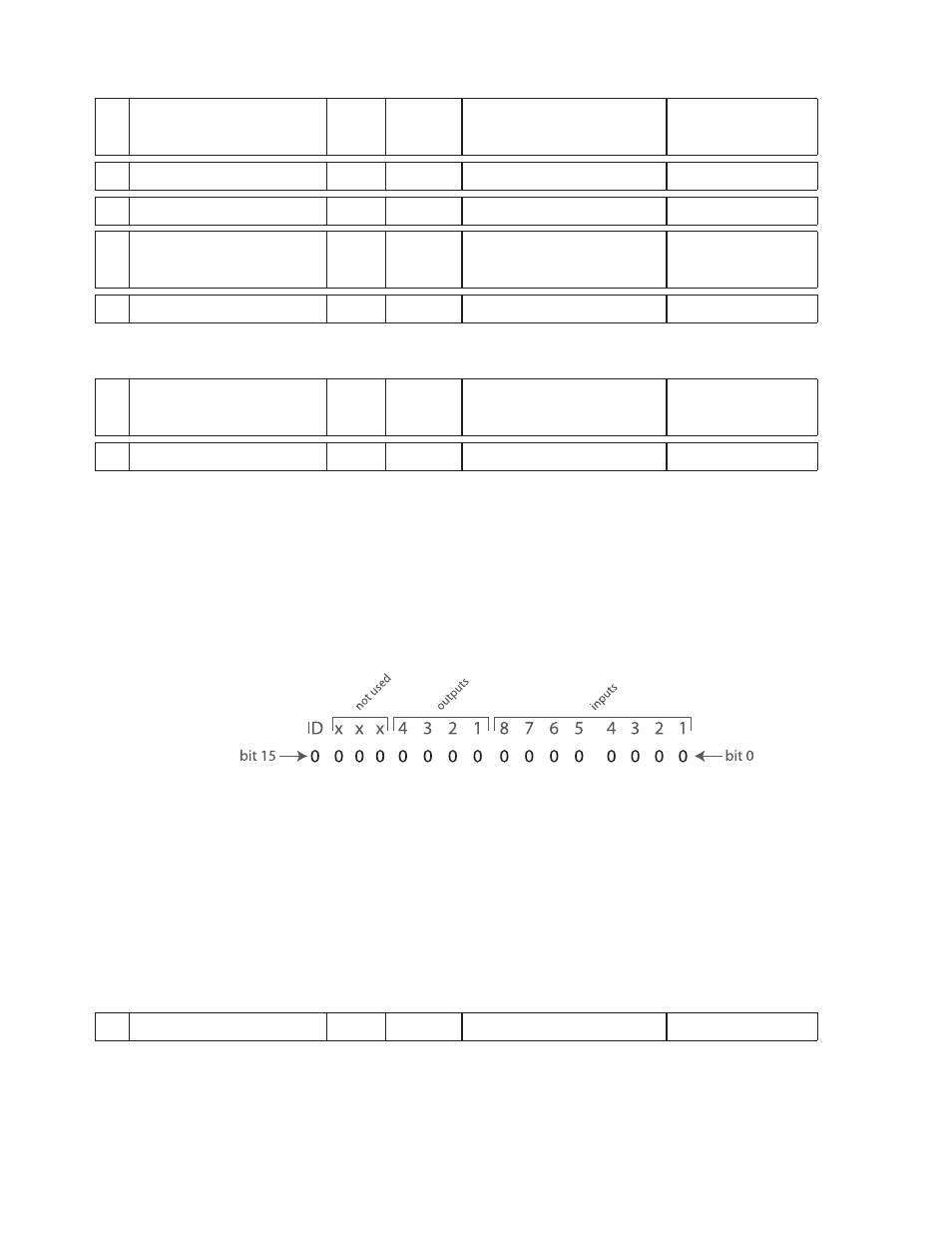
Details when executing the “RLy” command:
BLu, STAC6, SVAC3 and STAC5 drives
The bit pattern of the “y” register breaks down as follows: bits 0 - 7 represent the states of top board inputs 1
- 8, respectively; bits 8 - 11 represent the states of driver board outputs 1 - 4, respectively; and, bits 12 - 15
are not used. For all I/O bits 0 - 11 (inputs 1 - 8 and outputs 1 - 4), a state of “1” means the optically isolated
input or output is open, and a state of “0” means the input or output is closed. Bit 15 represents the ID bit,
which simply holds a 1 if the IN/OUT2 or screw terminal I/O board is present and a 0 of it’s not. In other
words, for SE, QE and Si drives the ID bit will equal 1. For S and Q drives the ID bit will equal 0.
For example, if top board inputs 3 and 5 and top board outputs 1 and 2 were all closed, the response of the
drive to the command “RLi” would be “RLi=-29461” (1000 1100 1110 1011). For a more efficient use of the
“y” register it is recommended to mask off the ID bit and the other three not used bits. This can be done by
using the R& (Register AND) command with the “y” register and a User Defined register set with the value
4095 (0000 1111 1111 1111 1111). Following a register AND operation (&), this will reject the top 4 bits,
leaving the rest of the data untouched. For example, the command sequence would look like this.
RL14095
Load User Defined register “1” with the value 4095
R&y1
Register AND the “y” and “1” registers
RL0
Request the value stored in the Accumulator register “0” to which the
drive’s response would be RL0=3307.
z
Phase Error
074
Short
encoder counts
Servo drives only