Applied Motion RS-232 User Manual
Page 305
305
920-0002 Rev. I
2/2013
Host Command Reference
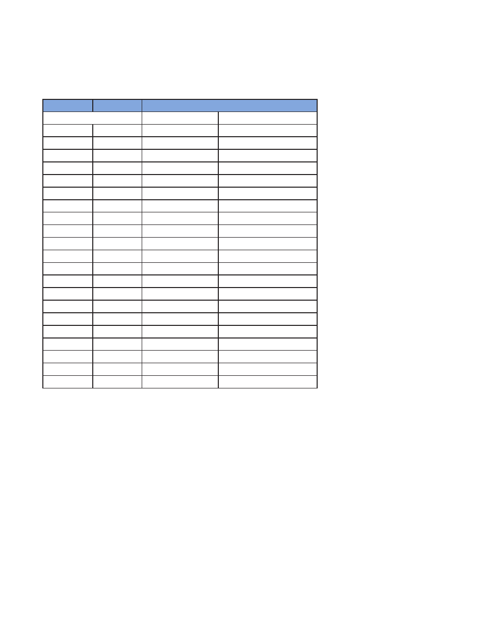
IO Encoding Table
Useful ASCII values for IO commands
On STAC5, inputs X1-X4 and outputs Y1 & Y2 are on the DB15 (IN/OUT 1) connector. Input X0 is the
encoder index signal. Inputs 1-8 and outputs 1-4 are on the DB25 (IN/OUT 2) connector.
Character
hex code
Signifies
ST5 & ST10
STAC5
X0
0xB0
encoder index signal
encoder index signal
X1 or Y1
0xB1
input X1 or output Y1
input X1 or output Y1
X2 or Y2
0xB2
input X2 or output Y2
input X2 or output Y2
X3 or Y3
0xB3
input X3 or output Y3
input X3
X4 or Y4
0xB4
input X4 or output Y4
input X4
X5
0xB5
input X5
n/a
X6
0xB6
input X6
n/a
X7
0xB7
input X7
n/a
X8
0xB8
input X8
n/a
1
0x31
n/a
input 1 or output 1
2
0x32
n/a
input 2 or output 2
3
0x33
n/a
input 3 or output 3
4
0x34
n/a
input 4 or output 4
5
0x35
n/a
input 5
6
0x36
n/a
input 6
7
0x37
n/a
input 7
8
0x38
n/a
input 8
L
0x4C
low state (closed)
low state (closed)
H
0x48
high state (open)
high state (open)
R
0x52
rising edge
rising edge
F
0x46
falling edge
falling edge