Casella CEL CEL-414 User Manual
Page 13
The interface uses four lines, two of
which are used for data transmission,
while the other two are for the hand-
shake request to send and clear to
send signals. Each digital output con-
sists of five bytes which describe the fre-
quency weighting, time weighting,
parameter selected, and its numeric
value. Use of the pause and reset func-
tions will also be indicated. More detailed
information on the output and input facili-
ties will be found in Sections 3.5 and 3.6.
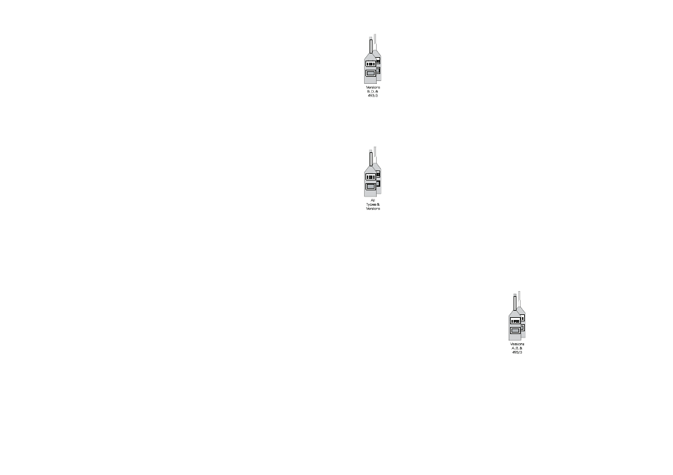
3.2Control Facilities
The functions of the various controls are
identified by the legends marked along-
side them on the instrument front panel
as follows, (see Figure 2).
ON-BAT-OFF
This three position slide switch is the
main on/off control for the instrument. It
provides the following settings:
OFF
No power is drawn from
the supply, nor any
function performed,
ON
All instrument functions
are available as
described below,
BAT*
The on-load battery
voltage is displayed,
while all normal
functions continue to
be performed.
Note*: On CEL-493/3, BAT position is also used
while setting the SEL event threshold
level and onset time.
Similarly, on C and D versions, the
BAT position is used while setting the
threshold for OSHA and DOD
measurements.
When the instrument is first switched
ON, the start up messages CEL to-
gether with the software issue number
appear on the digital display, changing af-
ter about five seconds to the instrument
type number (for example 275) with the
instrument version letter (A, b, C, d or E).
The analog bar graph steps along its seg-
ments to indicate that the microproces-
sor self checking procedures are being
operated. When this test has been com-
pleted satisfactorily, all measurement and
calculation functions become available.
Should the instrument fail the self test,
an error message will be displayed as de-
tailed in Chapter 12.
P-I-F-S (Time Weighting Switch)
A four position slide switch that selects
the time weighting required in the RMS
detector. It provides the following stand-
ardized settings:
P
Peak: <100 µs,
I
Impulse: 35 ms rise time
and 1500 ms decay
time,
F
Fast: 125 ms,
S
Slow: 1 second.
A-L-FA-FL (Frequency Weighting &
Filter Switch - A & B versions and
CEL-493/3)
This four position slide switch provides
selection of the linear (flat) response or
the built-in A-weighting network, and the
use of external filter sets. The following
options are provided:
A
Internal A-weighted
network,
L
Linear response of
instrument (+0.5/-3 dB
typical points),
80 (Hi) Range 3.5 Hz
to 70 kHz,
General CEL Sound Level Meters Handbook - Page 9